Shapeoko 3 XXL rigidity question

So I ask all the want to be engineers, weekend tinkering, toaster dismantling, mad scientist like my self this.
Do you think the SO3 rigidity suffers because of the wheels?
Do you think if it was fitted with linear guide rails that it would increase it’s rigidity?
I concede that adding weight to a base would also help to increase rigidity and even accuracy potential but are the wheels still the weakest link?
Remember, I’m talking rigidity. I understand the belts pose a whole different problem with power but not so much rigidity.
Ray

Yes, linear guide rails would be a huge improvement, and also a reversion to the original prototype (see the Kickstarter campaign).

Sonny Jeon, @chamnit has a fascination with an old poem, which I share, “The Wonderful ‘One-Hoss Shay’ ” — it pretty much sums up the difficulties here. To recap (as I understand it):

Weak point(s):

  • Shapeoko 1: X-axis plate thickness, X-axis rail (there was only one), single drive motor for Y-axis
  • Shapeoko 2: Makerslide load limits, possibly 6mm belts (but if so, because of friction/grip issues)
  • Shapeoko 3 (pre Summer 2016): — if spindle mount was placed at lowest possible point, flat X-axis plate, maybe still X-axis plate after that, possibly 6mm belts (but if so, because of friction/grip issues as noted above)
  • Shapeoko 3 (Summer 2016 and later incl. XL and XXL): Delrin V-wheels, maybe Z-axis belt (jury’s still out on that until I put together a test machine and finally do more than list parts and reference a sketch I can no longer find for an Acme screw upgrade)

All of this sort of thing is easy to see in hindsight, but at the time, while doing the engineering, well, I think the Shapeoko is an amazing engineering design (and good looking, too! The Shapeoko 1 is impossibly cute in person, the Shapeoko 2 ought to be in an industrial design museum somewhere, the Shapeoko 3 looks decisive and purposeful, and I love the proportions of the XL, and the XXL despite appearing massive has a balance of shapes and proportions which belie that).

If you haven’t looked through Edward’s previous designs — he also posted a bunch of prototypes — you’re missing out on a well-spring of ideas.

Moreover, the belt-driven Z-axis is a huge advantage for a CNC machine for novice use — the worst thing which should be able to happen is the belts skip in a crash, and the Delrin V-wheels similarly are a big advantage, in the rare instances something does break, well, thus far, it always seems to be the V-wheels, and, they’re cheap.

The linear guide rails would also hugely increase the expense, a couple of hundred dollars, per axis, I believe — if you can justify that, well, you’re going to make the rest of us very jealous.

2 Likes

I don’t think there are many choices to improve rigidity, especially economically. Edward has come to a fairly price optimal design with the SO3.

If you have the money, adding two linear slides directly attached to each of the beams would improve rigidity up to a point but making sure they are flat, straight, and perfectly parallel is hardest part. And as Will mentioned, it’s stupid expensive when you need long ones.

Personally I think the weakest point in the SO3 deign is the X axis bearing arrangement. It went from 8 bearing sets in two planes on the SO2 down to 4 bearing sets in one plane. Rigidity depends highly on how well those bearings are preloaded, which is done by the precision shim between them. I recall that there was a batch of SO3s that had precision shims that were not to spec causing a little looseness.

Perhaps the lowest hanging fruit would be to make an adapter to have bearing sets ride flat on each side of the V feature of the rail so you up the number of bearing sets carrying the load from 4 back up to 8.

2 Likes

Ah, good point about the bearings — I always forget those. In that case, we would prioritize the bearings by X-axis plate needing to have precision shims perfectly matched to the thickness of the inner races. There’s a bit on that on the wiki — at one point, one guy was selling copper ones which one could stone down to the perfect thickness.

Perhaps I should have been more clear. Rigidity isn’t an issue for the SO3 and what it was designed for. It’s better than anything else on the market in this price range. If you want better rigidity, you’re looking at machines that cost several thousand to over $10k. It usually gets better as you spend more, but that’s not always guaranteed.

That said, the only instance I’ve seen in forums with tool chatter is when milling aluminum in the y direction (applies load on the 4 X bearings). They just milled in the x direction (applies load on 8 Y bearing sets).

FWIW, I studied bearings in my PhD dissertation for use in precision joints for space. They are really finicky and sensitive to tolerances. The precision shims are there to help ensure the bearings are running coaxially. The Delrin sleeve has a stop feature inside for the outer races. This prevents over loading the bearings. IMHO, it’s a great design, but once you get into the right range of spacing, the Delrin stops will deform a bit and you won’t be able to preload that much more. You want to be just in this range if possible. From what I can tell, they should be already.

2 Likes

I’m not an engineer but I have designed all the piping for launch pad 17b at Cape Canaveral. With rigidity in my mind, I am planning my next experiment for my Shapeoko. I have some 2 1/2" x 1/4" angle iron and I’m thinking cutting four “L”'s for mounting brackets at the corners. Those I would bolt down thru the rubber mat and the concrete/plywood base. I would also add a fifth bolt in the center (where I have an 8" wide plate under the base board). I’m thinking that to maintain perfect levelness of the machine I would tighten the bolts with a torc wrench to apply exactly the same force to each corner and the middle. Than the machine would be solidly anchored, vibration isolated and level. The main downside would be the huge pain it will be to remove the machine from the enclosure (maintenance/repair). I do a lot of over the board stuff but I’ve also eliminated all the sun’s heat gain on my shop (sits in direct all day sunshine) here in Florida. SO wonderments can be reality and reality can be a real wonderment. YMMV (I really like that acronym, Thanks someone).

1 Like

I believe I might have some of those out of spec. Shims. I just haven’t wanted to tear it apart yet and with the wood projects I’ve been doing, my XXL is more than accurate.
The SO3 is I believe is the best bang for the buck.

1 Like

What are the Torsional Stiffness, Repeatability, Programmable Resolution, and Backlash specifications for the latest Shapeoko 3 XXL? Are they comparable to those of the Stepcraft-2/840(https://stepcraft.us/product/stepcraft-2840-desktop-cnc-system/)

So, a general question for the engineer types on this topic: On bigger machines, many are using larger bearing rollers on a smooth rail combined with a rack and pinion gear system as the drive component. So could you achieve the rigidity you are looking for simply by ditching the belts for a rack and pinion drive on the X and Y axis? It seems it would be cheaper than going with linear guide rails.

@chamnit should be able to address the physics numbers.

Resolution: the programmatic resolution for the X- and Y-axis is 40 steps/mm (~1000 steps/inch). This was determined using inputs of 200 steps/rev, 8 micros/step, 20 teeth pulley, and 2mm belt pitch.

Repeatability / precision: - If tuned properly you should be able to get to a resolution of 0.003″ –- 0.005″ (~0.075mm – 0.127mm) — better is achievable with careful setup and an upgraded machine and suitable toolpath strategies.

Per http://www.sdp-si.com/D265/PDF/D265T003.pdf backlash is negligible.

The discussion here may be helpful, since the X-Carve and Stepcraft are fairly similar: http://carbide3d.com/vs/shapeoko-vs-xcarve/ in terms of extrusion.

What about Torsional Stiffness?

Interesting that Stepcraft apparently no longer quotes stiffness for their 2/840 (now D840?). I’ve asked them why. They used to claim a XYZ Torsional Stiffness with 20N (~4.5 lbf) of 0.0039 - 0.0055 inches.

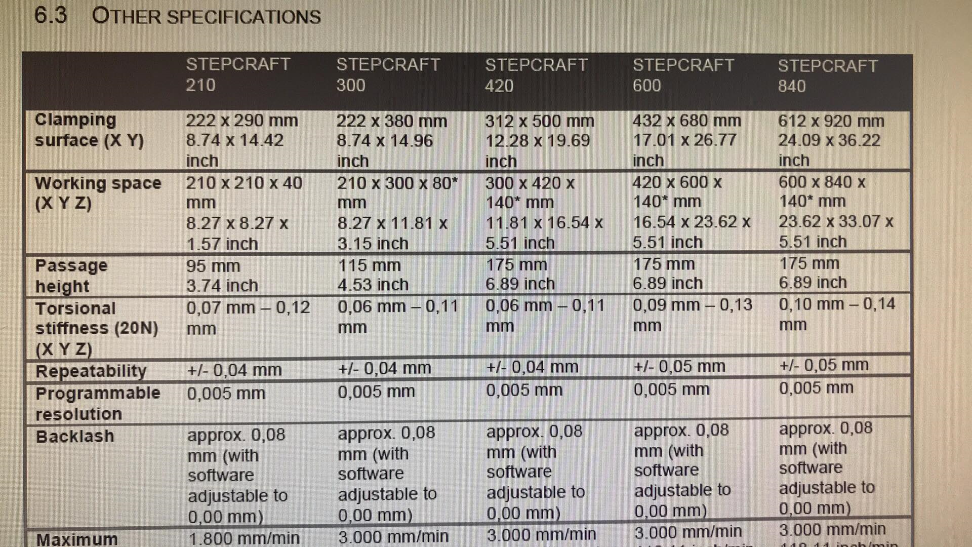
Yesterday Stepcraft responded that their torsional stiffness spec. has not changed.