I just went through this - again - with my Pro (4) Standard. It’s complicated, and the way I did it involved a tablesaw and bandsaw, so it’s not for everyone, but here it is:
- First thing, at least with my machine, was to re-establish the cutting boundaries. Mine came setup with 445 for X and 444 for Y. That was 6.5mm smaller than I can cut in X, and 8mm too big for what I can cut in Y, which led to problems with some jobs. Here’s the procedure I went through to establish the cutting boundaries:
1a) With the machine on, in Carbide Motion (CM), jog to the SW corner, then jog as far left and towards you as you can, making sure you don’t hit either physical stop. You can start in FAST, but if the machine won’t go further, lower the speed to 1mm or even .25mm. Switch the display in CM to show Machine Position, which will be negative since (0,0) is the upper right.
1b) If you have almost hit a stop (I’m talking like a mm here), write down the Machine Position co-ordinates. Note the the closest Y position will be over the front of the hybrid table, but that’s OK - I actually made my slats longer to gain more useful table (see photo later).
1c) If you haven’t hit the stop and the machine won’t jog further, measure the gap. Add that to the Machine Position displayed and write that down.
1d) Quit CM (this is important!). Start up Carbide Create, go to “Help”, Choose “About” (on the Mac,“About” is in the first menu), then select “Open Data Directory.” In there is a shapeoko.json file. Duplicate it and rename it something else just for safety.
1e) Open the original shapeoko.json file with Notepad or TextEdit and change the following lines:
    "travelX": -451.50,
    "travelY": -436.75,
Except use the values you wrote down (make sure they’re negative since (0,0) is the upper right in Machine terms). Save the file, making sure it has the exact name and extension shapeoko.json (no “.txt”).
1f) Restart CM - this will read in the json file. Re-initialize the machine. Load a Vee bit. Jog all the way over to the front left and make sure that nothing has hit a stop, but that’s it’s very close. If so, you’re now safe when jogging AND when running a job in CM (it’ll warn you if it goes over the limits).
-
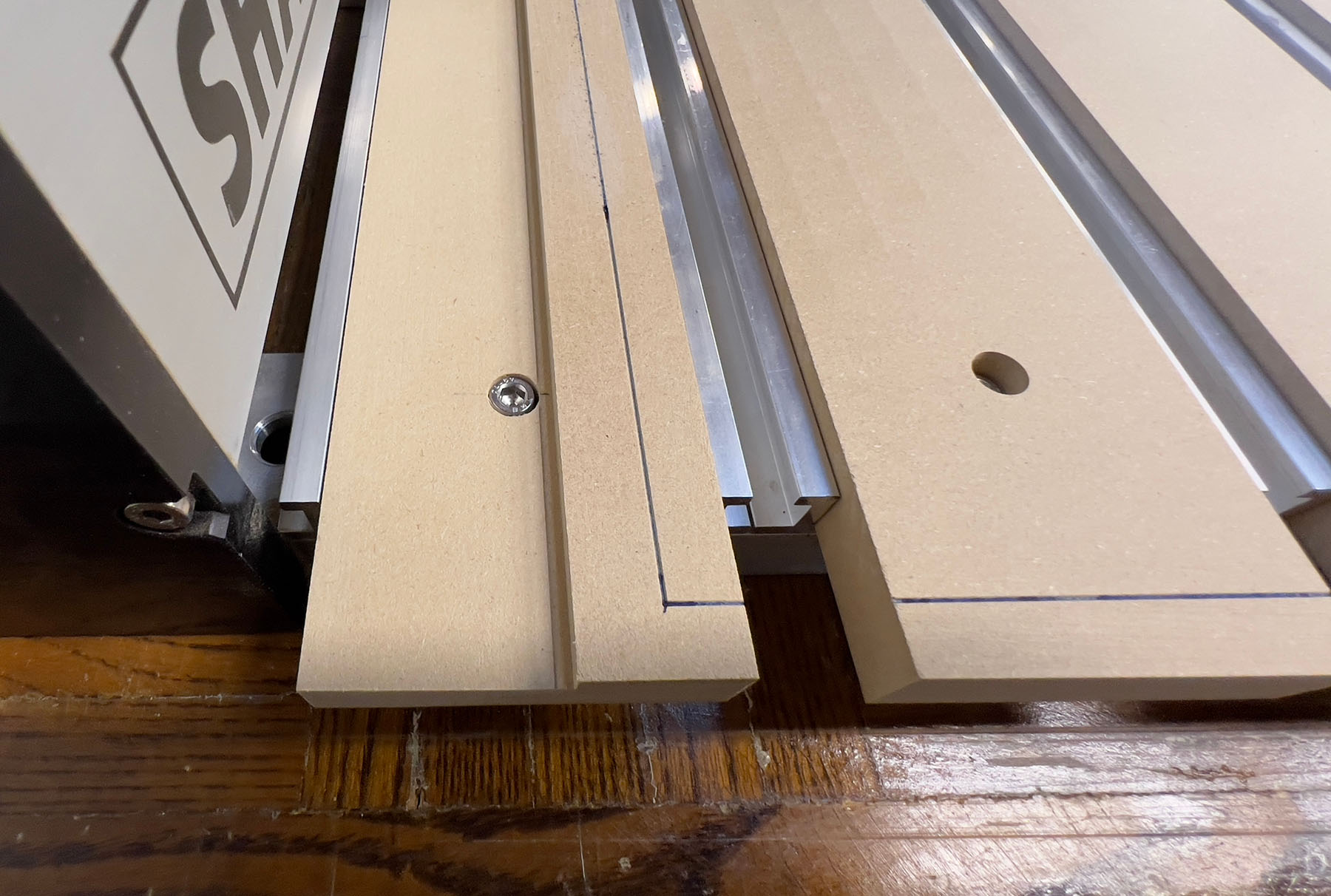
Now get your MDF boards sized to fit the hybrid tracks (74.5mm wide works well), and long enough and install them. If you saw that your closest Y is beyond the hybrid tracks, you may want to make your MDF boards longer to give you more table surface. Here’s a close up of the front left of my spoilboard:
Notice the MDF extends about 50mm in front of the aluminum tracks. You’ll also note the blue line, which is the centerline of the cutter at its extremes. Pay no attention (yet) to that the MDF is cut down outside left, more on that later. -
I recommend creating a Quick Action to save this lower left Machine Position as a zero position. You’ll want it for the spoilboard flattening job. And while you’re here, since you have the Vee bit centered over the front/left, lower the bit until it’s just above the Spoilboard and mark this (0,0) location. I cheated, ran the router, lowered the bit carefully until it just touched the spoilboard, and then jogged up, back to zero, then jogged right to create some lines, which intersect at this zero point.
-
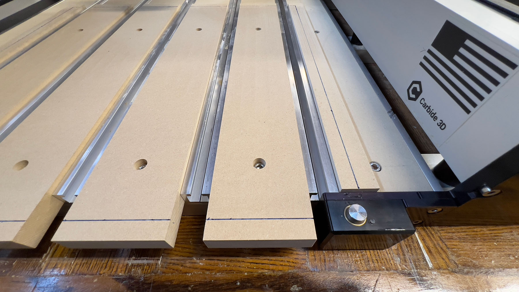
Now you need to take some measurements so you can exclude the BitSetter in your flattening job. Measure from the zero point to the right edge of the 5th MDF slat (just before the Bit Setter) and call this BSX, and also measure up from zero point to the front of the 6th MDF slat and call that BSY. Here’s a photo of the area:
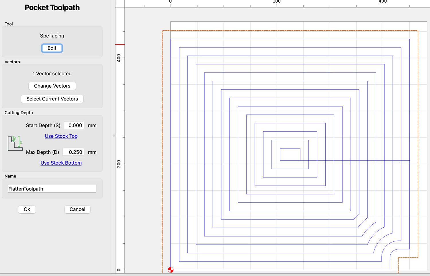
5a) Now you can build the flattening job. For this, you’ll have to know the diameter of the bit you’re using, whether that’s just a ¼" end mill or the 1" McFly cutter (recommended), since the area you’re flattening is bigger than the extremes you just setup by the radius of the bit all around.
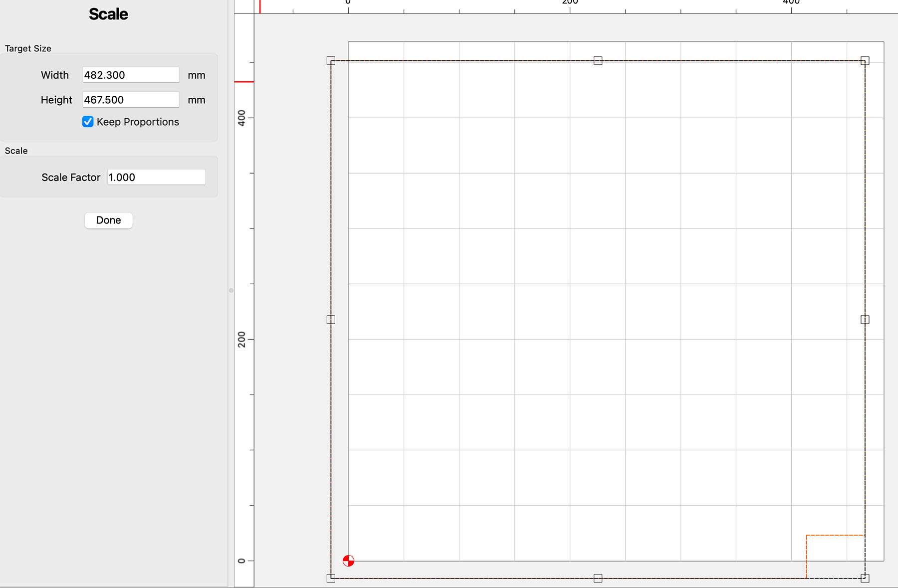
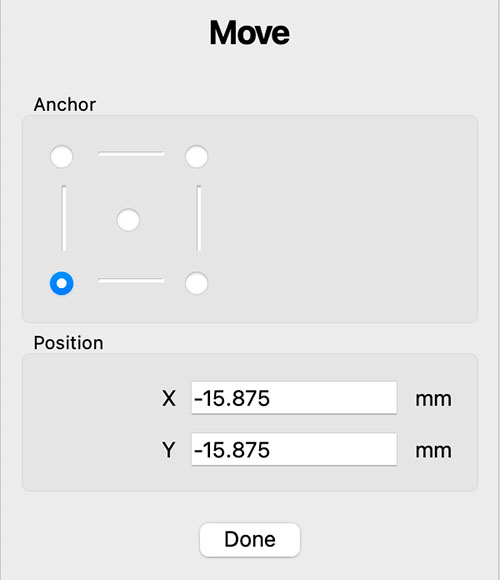
5b) For my Pro (4) Standard with BitSetter and using a 1.25" fly cutter (not the McFly), I built this file in Carbide Create:
Spoilboard Facing Avoiding BitSetter 0.25mm below Z-Zero.c2d (44 KB)
Which has this setup:

And looks like this:
With this zero point:
5c) You build it from two rectangles:
• First is the large rectangle, whose Width is travelX (absolute value) plus the diameter of your flattening bit (BitDia from now on), and whose Height is travelY plus BitDia. I found I had to subtract 1mm from these dimensions to avoid warnings in CM.
• Move the Lower Left of the rectangle to -BitRadius for both X and Y. I’m using a 1.25" diameter fly bit (not the McFly), so those values are shown there. For the McFly, those values would be -12.7mm (half the 1" diameter).
Note you have to size the rectangle before moving it into position, since resize does so around the center, and so the lower left will move on a resize in CC.
5d) Now you need to build a rectangle representing the BitSetter area to avoid:
• The width of this rectangle is travelX minus BSX plus BitDia (from Step 4).
• The height of this rectangle is BSY plus BitDia.
Note these dimensions aren’t super-critical, as the BitSetter protrusion is several mm away from the edges you measured.
• Set the Lower Right of this rectangle as follows:
• X is the Width of the big rectangle
• Y is -BitDia (yes, negative)
5e) The next step is to use CC’s Boolean Subtraction to subtract the smaller rectangle from the larger one. Select the larger one first, then Shift-Click to select the smaller, then in the Boolean box that shows up, click the right-most icon for Subtract:
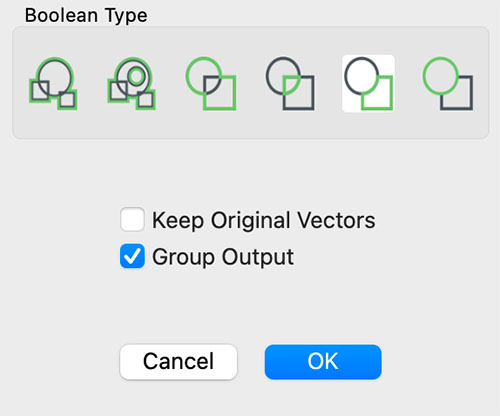
And choose “Group Output” to end up with one object.
-
Now it’s pretty straightforward, create a pocket toolpath with your flattening bit. Since zero is at the current top surface, I chose to pocket down 0.25mm for starters. I ended up running it twice to get all my slats surfaced (resetting zero after the first pass).
-
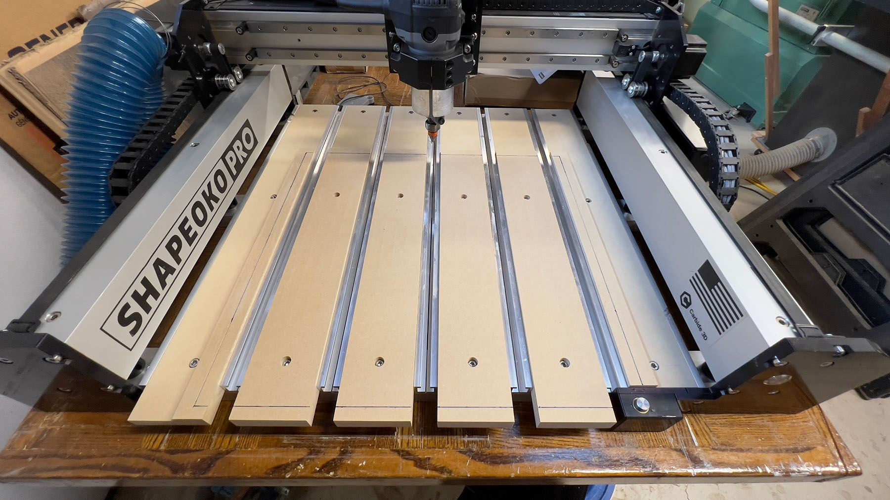
After flattening, you’re left with a future potential issue with workpieces that are larger than the millable area of your CNC. Since the flattened area is lower, these workpieces will hit the non-flattened areas and thus all heights will be off (and maybe angled, too). What I decided to do, as you can see in the above photos, is to thin the MDF so that it’s basically at the aluminum track height outside of the millable area. This way anything that extends beyond is not affected, height-wise.
• For the leftmost and rightmost slats, I did this on the tablesaw, ripping on edge with the blade height just enough to reach the millable area.
• For the back of all the slats, I resawed then on a bandsaw, only going as far as the millable area couldn’t reach.
If you don’t have this equipment, you could rig up milling jobs to cut “pockets” into each slat, one at a time, fixed to the table with all the other slats in place. For the left and right slats, you will either need to take two setups, or have a 45º setup to fit.
Here’s my end result:
I did run that Vee bit at like a 1mm depth all the way around the extremes to mark the bit center boundaries.
Hope this helps someone, sorry it is so long.