I adjusted the chiploads to provide what seemed like a reasonable machine force of ~ 3.33 lbf. Then I checked the endmill manufacturer’s recommended maximum chiploads for the material being cut. Yoniko provides feed rates and speeds for their endmills from which the workbook can calculate chiploads. FYI, I corrected an error I found in the endmill deflection calculations when shank diameters exceed cutter diameters. The tables above are now corrected for 0.001" of maximum endmill deflection. Note that the Yonico endmills aren’t rated for Aluminum though. Here’s the spreadsheets showing details.
0.25 and 0.125 Inch Endmills.zip (114.4 KB)
2 Likes
I’ve been using VCarve, so don’t know much about Carbide Create. But I believe you should be able to have it safely plunge slowly enough to that depth without ramping. I also don’t know how to have it cut a slot (WOC = endmill diameter). DOC = WOC = endmill diameter seems to be a “standard” for endmill manufacturers’ feeds and feeds charts. I assumed that WOC = endmill diameter was the case with CC’s too (some of which show DOC more than WOC). 3.3 lbf seems plenty safe to me, but you can always start at some feed rate and decrease/increase it as much as +/- 100% in Carbide Motion while running. Maybe others with more experience will chime in!
Very interesting approach, my interest is piqued (again). If I am not mistaken, dropping all constants from the equations,
- Torque is power over RPM.
- Power is MRR over K_factor
- MRR is WOCxDOCxfeedrate
- Chipload is Feedrate/(NbFlutes x RPM)
- cutting force is torque over endmill radius
so cutting force is proportional to (torque)/(endmill radius)
so to (power)/(RPM x endmill radius)
so to (MRR)/(K_factor x RPM x endmill radius)
so to (WOC x DOC x feedrate)/(K_factor x RPM x endmill radius)
so to (WOC x DOC x NbFlutes x Chipload) / (K_factor x endmill radius)
What this table is telling me is that since you are choosing a target cutting force (3.33lbf), for a given endmill and WOC/DOC the key is to produce a constant Chipload / K_factor ratio ? Which gives these “surprising” chipload variations, that in fact onlty reflect the natural variations in K-factors of the listed materials.
A few follow-up questions:
- When looking at the values, the CL/K ratio is indeed almost constant, EXCEPT for the 6061 Al for 1/4’’ and 1/8’’, and Acrylic for 1/8’’. Did you tweak those differently ?
| CL | K | CL/K | CL | K | CL/K | ||
|---|---|---|---|---|---|---|---|
| MDF | 0.0037 | 35 | 0.000105714 | 0.0018 | 35 | 5.14286E-05 | |
| Torrey Pine | 0.0025 | 24.11 | 0.000103691 | 0.0012 | 24.11 | 4.97719E-05 | |
| Yellow Poplar | 0.0024 | 22.68 | 0.00010582 | 0.0012 | 22.68 | 5.29101E-05 | |
| Santos Mahogany | 0.0018 | 17.5 | 0.000102857 | 0.0009 | 17.5 | 5.14286E-05 | |
| Baltic Birch | 0.0010 | 9.45 | 0.00010582 | 0.0005 | 9.45 | 5.29101E-05 | |
| Acrylic | 0.0020 | 20.06 | 9.97009E-05 | 0.0020 | 20.06 | 9.97009E-05 | |
| 6061-T6 Aluminum | 0.0005 | 3.34 | 0.000149701 | 0.0010 | 3.34 | 0.000299401 |
-
I missed the key part of the story: why would it be the best strategy to aim for a constant cutting force?
-
why 3.33lbf ? It’s such a specific value that I guess you derived it from something else ?
-
What happened to the 18lbf machine limit we discussed earlier ? The spreadsheet now has 3.33lbf as the machine limit
EDIT: and I realize now that this discussion should rather continue in the “origins of chipload” thread ? 
4 Likes
The ability of the CNC machine to counteract cutting force limits performance if the cutter and spindle don’t. Counteracting those cutting forces causes deflection which causes the cutter to deviate from the intended location as well as other nasties. Even though Shapeokos can supply up to 18 lbf, the resulting machine deflection would likely be unacceptable. That’s probably why @Vince.Fab (and @Luke) are replacing at least some of the V-Wheels with linear slides.
3.3 lbf force was kind of arbitrary but seemed like a relatively safe value based on Stepcraft’s D.210 specs.
I think I’ll add the option of having feed rate determined by allowable force (perhaps determined by deflection measurements) rather than chipload. That seems to make more sense to me since actual chipload values aren’t very important if they are kept below the cutter manufacturers’ recommended maximums.
I’m confused, are you saying that 3.3lbf is enough to deflect the Shapeoko? Have you done any measurements? I find it hard to believe, it seems very low, more like the deflection of the XCarve. I saw a video of someone standing on the frame and the deflection was not noticeable (albeit not measured with a caliper).
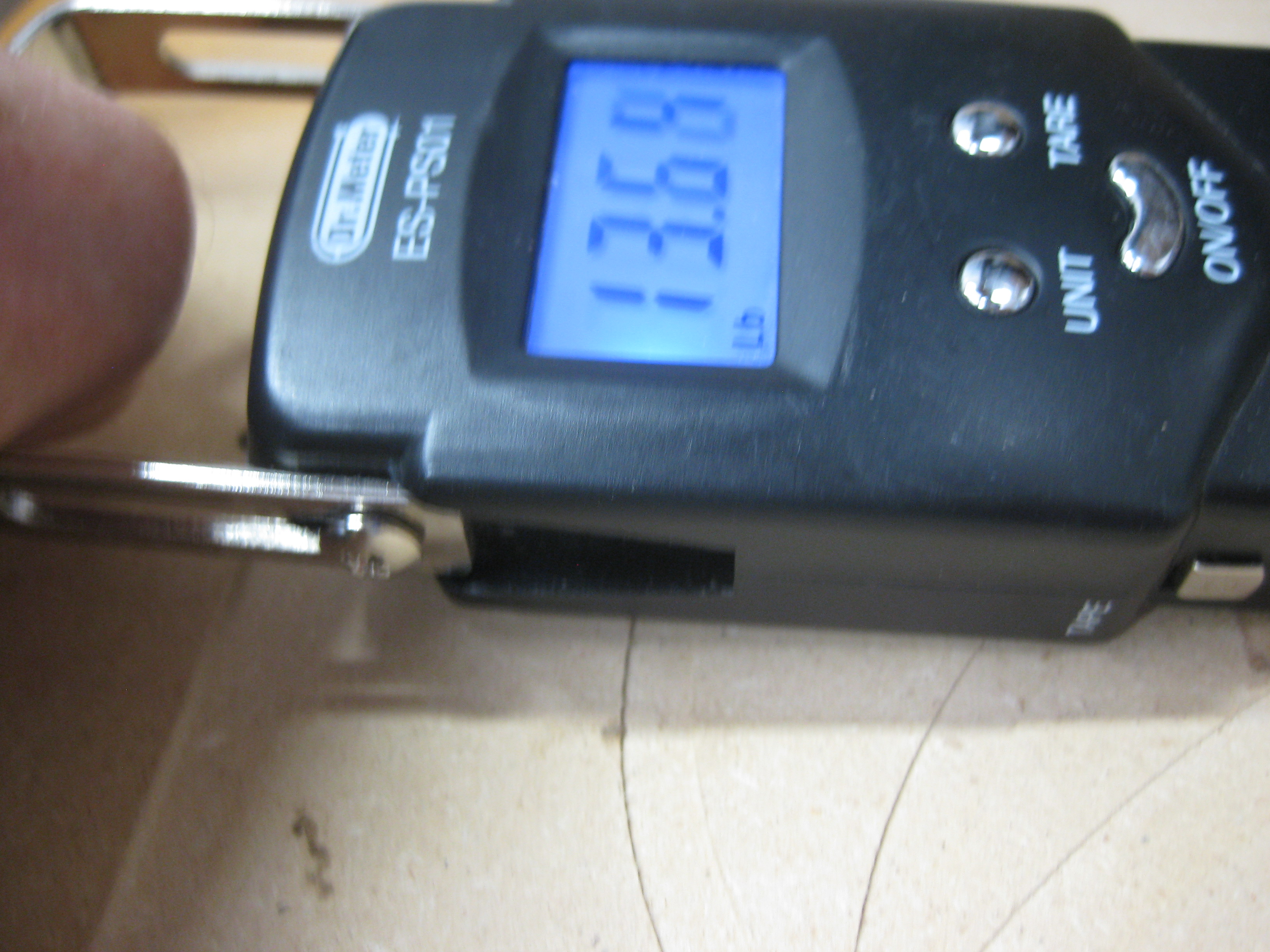
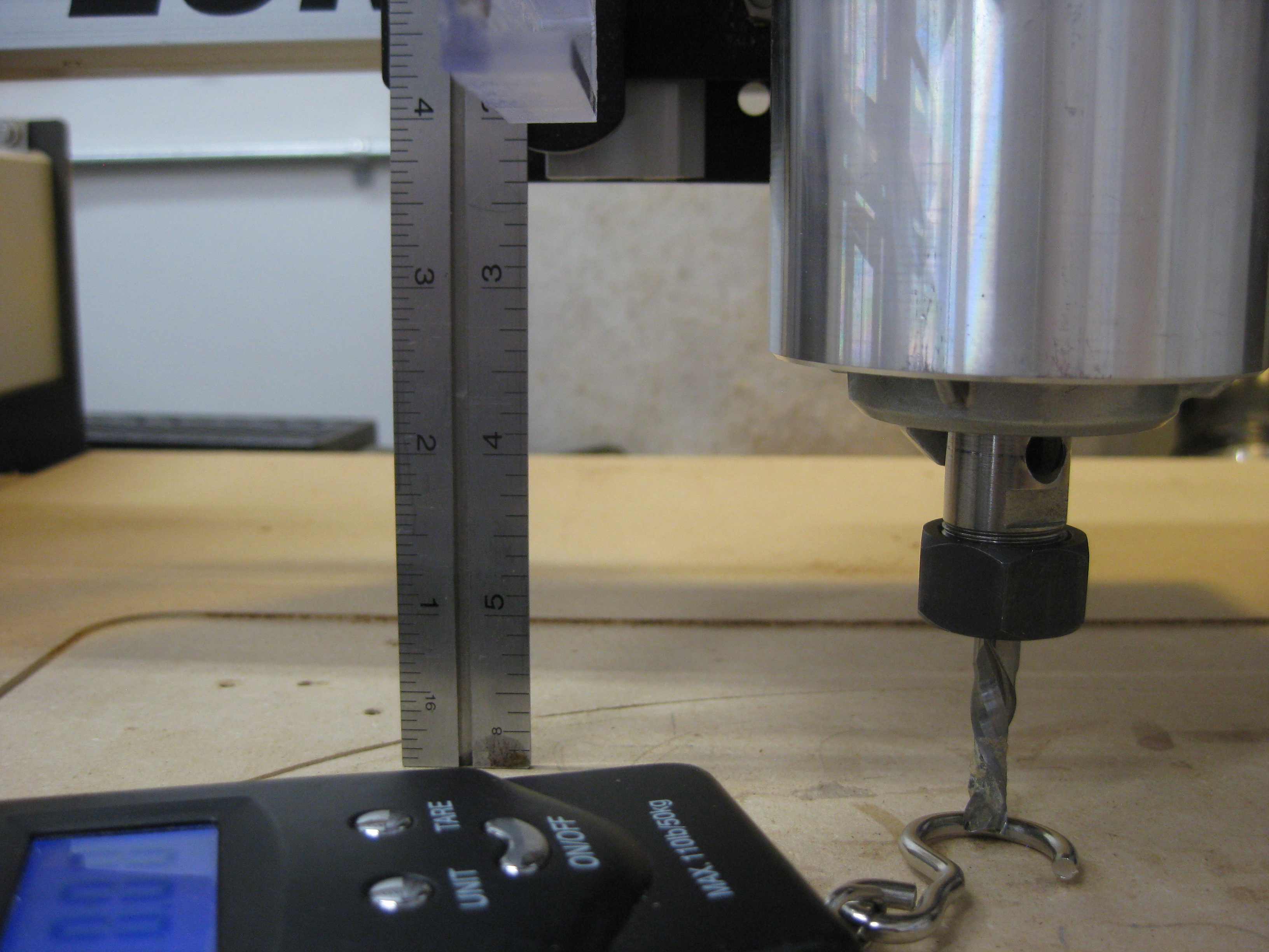
The cutting forces appear at the bottom of the endmill, so that’s where deflection needs to be measured. I measured about 14 lbf for 1/16" deflection along the X-axis and about 10 lbf for 1/16" deflection along the Y-axis.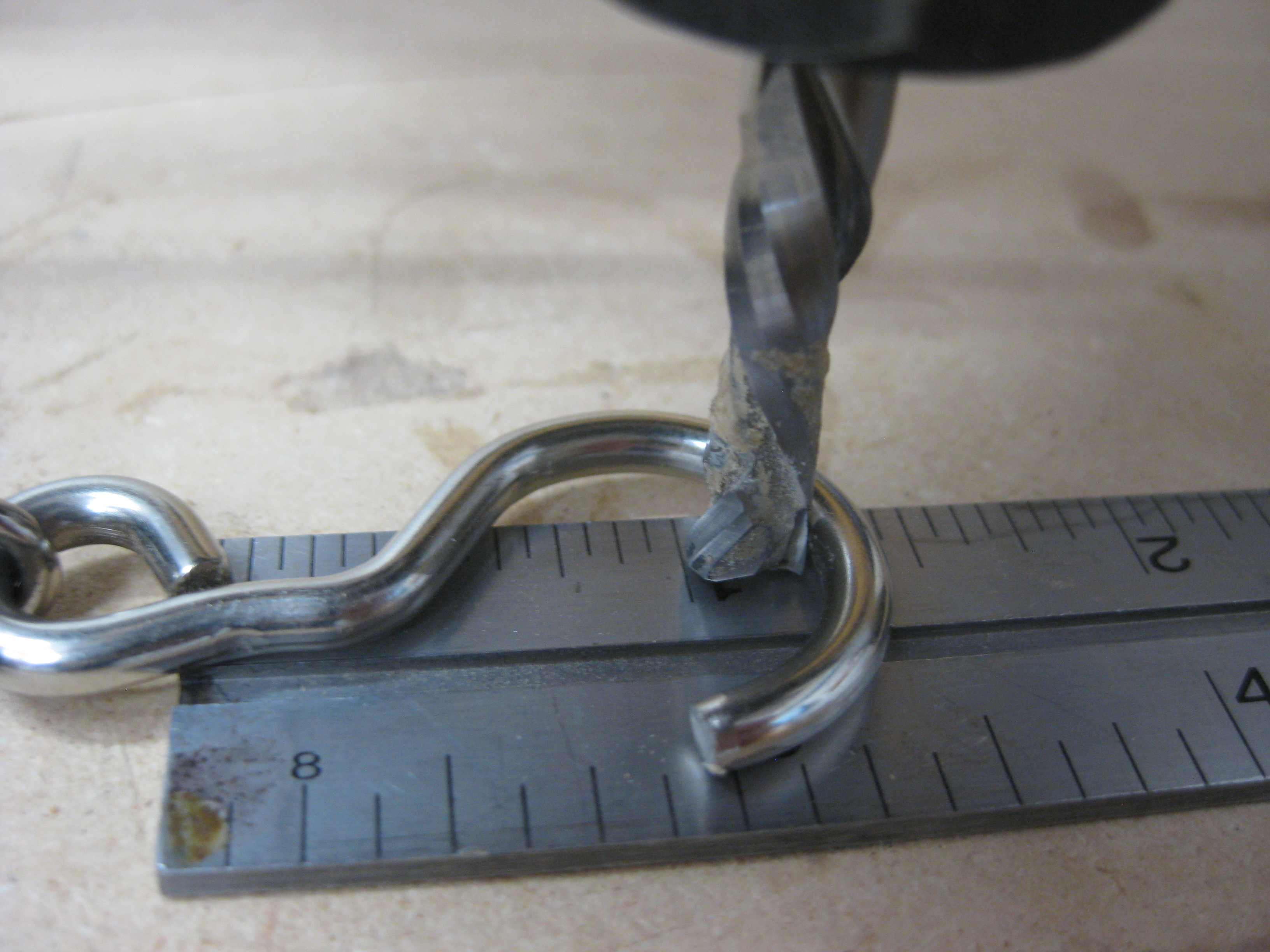

3 Likes
Well, as long as they are above the golden value of 0.001’’ I guess.
Also, how did the thermal aspects disappear from the equation? Just because of high RPMs hence smaller forces hence small amount of heat?
I hate to bring this back to the table but 27000 RPM will not be acceptable for everyone.
1 Like
Ok, we know the Z axis is the weak link but how do we get from 10 to 14lbf to 3.3lbf? It would be interesting to see what measurements a Shapeoko with HDZ gets.
1 Like
All of the V-wheels are weak links, it’s just a matter of degree. I figured that 1/52" deflection would be a lot more acceptable than 1/16", so it was kind of arbitrary I guess.
1 Like
Ok so I went to my workshop and replicated your experiment. I placed the spindle on the center point rapid position with a 1/4in 201 endmill. I used our luggage scale and measured 20lbf along the X axis and 15lbf along the Y axis. I have an EasyTram Z plate and upgraded V wheels from Mr Beaver.
1 Like
It appears that even BW, who probably originated the (now discredited?) “chip cooling” myth, isn’t even a believer anymore. The following shows GWizard recommending a 0.0002 chipload.
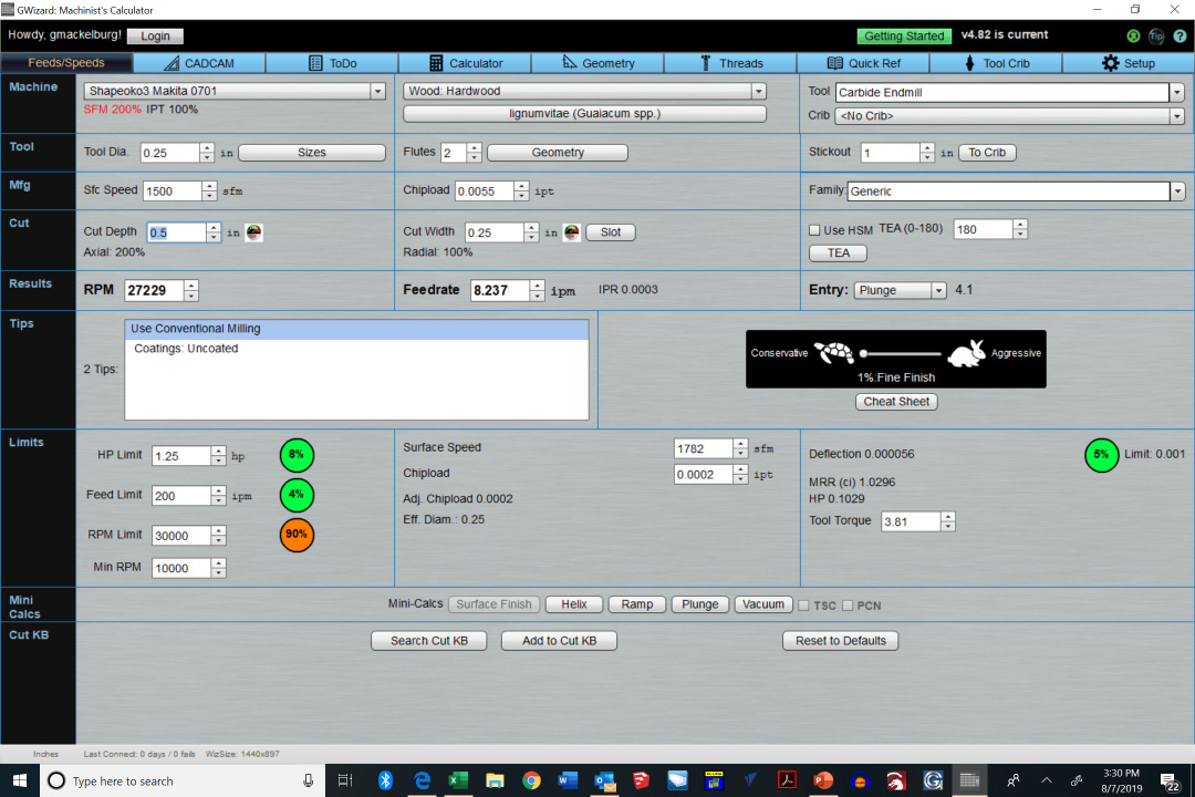
IMO the thermal aspects never entered into the equation, but I wonder how much wood burning would result from the slow feed rate shown above!
The table was just a simplistic “straw man”, it’s easy enough to generate more of them. I’ll add the force driven feed rate option when I get around to it.
Approximately an extra 5 lbf on both axes for a 1/16" deflection then? Note that the amount of spindle and bit stickout (their vertical position with respect to the load carriers) will affect the measurements too.
My Makita Spindle is all the way in the mount, bit stick out is 1 3/16in. Measured about 1/16in above my wasteboard which is 3/4in above the OEM wasteboard.
1 Like
To be fair, it only outputs this 0.0002" chipload when the turtle/hare slider is at the minimum (1%), and goes up to 0.001" as soon as one selects at least 15% on the slider. This slider is probably the top reason why I don’t really use GW anymore, since I have yet to figure out what part of this slider range is actually appropriate on a Shapeoko. As you noted, the 1% position might as well be called the “bit burnishing setting”.
If I know anything about me, I will want to experiment to measure actual endmill temperature depending on the chipload & K factor, to be convinced. I wanted to contribute to your K-factor database anyway by doing test cuts in as many different materials as I have on hand, so it will kill two birds with one stone.
Anyway, it seems to me that no matter what approach we take, we end up concluding time and again that anything in the [0.001" to max chipload for the endmill size/manufacturer] range will work, and that more specifically [0.001’‘-0.002’'] is better at high RPMs (while I still believe that at lower RPMs thicker chips are needed, but I have yet to prove it or convince myself otherwise)
You must have been close to having the X-axis stepper slip. Did you check that? What size Shapeko do you have? (My measurements were on the small one with a Makita fully lowered in the current stock mount and about 1/2" thick spoil-board.) So, in light of your measurements, what force would you put into the calculator to come up with an initial feed rate with that stick-out? (This link has some issues, but shows the basic idea.) Is your EasyTram Z plate pink? Do you have upgraded V wheels on all 3 axes? Does/will Carbide 3d sell them? ![]()
The stepper did not slip. I have the Shapeoko XL. The EasyTram is anodized redish (I prefer that to pink). Not all the wheels have been upgraded but the Z have and some of the others. I would like to finish the wheel upgrade but Mr Beaver had run out. Maybe Vince’s upgrade would also address some of the deflection issues.
1 Like
The researchers from the link you provided imbedded thermocouples in the workpiece to measure its temperatures near the cut. The temperatures measured there were around 450 degrees C. That suggests that the carbide endmills that they used were good for temperatures significantly higher than that. Aluminum melts at 660 degrees C. Pyrographers typically use tools with less than 571 degrees C tip temperatures. Most plastics melt at around 200 degrees C. So, why do endmills need to be kept “cool to the touch”?
Regardless, the proof is in the pudding and its nice when you can kill two birds with one stone, even if it may be guiding the lily. I recall @Vince.Fab mentioning an IR camera recently. That seems lot easier than the thermocouple approach.
I’m glad to hear your planning on measuring some K Factors!![]()
Holy Cow! Mitsubishi says their endmill coatings are good to 1300 degrees C!!!![]()
1 Like
How about using an infrared thermometer? It is a lot cheaper, more available and provides a temperature not a graphic depiction.
1 Like
Exactly what I was planning on using, I raided the kitchen a few minutes ago in search from our laser/IR cooking thermometer
2 Likes
True, I have no evidence that endmill temperature is necessarily bad. Just personal experience from bad and good cuts, BUT that might have been only a sign of rubbing vs not rubbing.
Also, I learned a new saying today (“gilding the lily”) !
1 Like