Shapeoko Pro XXL Enclosure - Working Height

Im just getting back to this again. been thinking about what y’all have said about the linear glides.

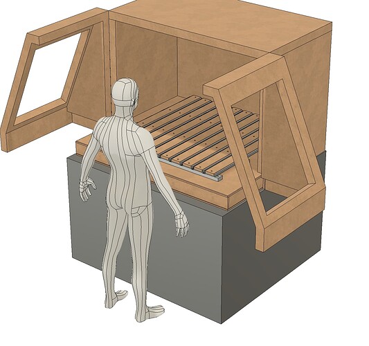
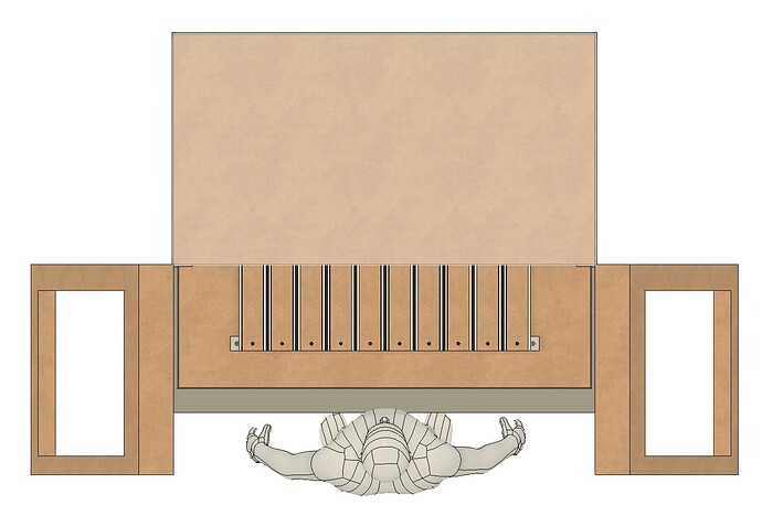
If I move the pivot point of the hinge back substantially, I can use SOSS hinges and get 90d rotation on the door with minimal intrusion into the space in front of the enclosure.

There is an added benefit that the setback on the hinges opens the area around the front of the machine for cleanup and maintenance.

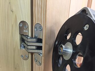
SOSS Hinge

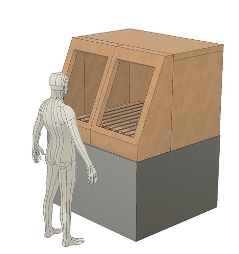
Updated Version
Ive also reduced the complexity and increased visibility in the door’s window.

Doors at 90d open (SOSS hinges open to 180d)

Vertical shot (note the minimal intrusion in front of the enclosure)

Sorry, the humanoid lost his binary clothing again.

open to any suggestions or feedback.

Any idea what those doors will weigh? As thick as you have them drawn they are going to weigh a lot. Probably the better part of 100lbs each.

they will be a lamination of 1/2" and 1/4" plywood and rock wool. not sure the exact weight but probably in the 30-40lb range.

Oh good thing! I was thinking it would be 2"+ of MDF. Beefy.

Its hard to tell what the clearance will be up front. The shapeoko comes to the very front center for bit changes, to the point where the spindle is overhanging off the front, and the Z is cranked up high. On the pro, I have the sweepy dust collection mounted in front of the spindle. I dont know if you can put the sweepy off to the side and not have it hit the Y rails.

So, room for the router, sweepy, and dust collector hose all in front of the bed of the machine, at a high Z height. Your sloped door looks like it could be close.

1 Like

I think the doors look real cool in the new drawing, but I’ve been thinking about the Soss hinges you’re considering for the shape of door.
If you want to go this way, I encourage you to build a mock-up door and seeing how the hinges react before committing to the design.

Soss hinges (sausages) can be great, I’ve installed them on full sized doors and access panel-type doors before… they can be tricky to install, but they have their place… although what you’re talking about here is a very atypical installation. (more on that in a sec…)

First and foremost - you’ll need to size them appropriately, so weight of the whole thing, and the thickness of your mounting stiles will need to be correctly sized. Refer to this chart if you haven’t seen this yet:


For example, for a 30 lb door, 30" wide, you’d be looking at two 1" hinges, or three 3/4" hinges… the larger you can go, the better.

The atypical part of this install, and the part that concerns me… is that these doors will be putting at least two axes of stress on the hinges… A typical door leaf just has one dimension of stress- it pulls out away from the jamb.
Your door is a 3-dimensional object (I’m sorry, I don’t know the names for the exact forces applied), but the center of gravity of the doors is well off to the side of the plane of the hinges. Due to this shape, the doors will want to sag where they meet in the center of the box. How much, I really don’t know - but they will.

In your drawing, the bottoms of the doors will sweep over the tabletop, so this sag may interfere with the ability of the doors to close easily. Soss hinges have no adjustability. The only adjustability is what you can do with the mortise pocket.

So, I’d strongly recommend building a simulated mock-up door and hanging it as you intend before going forward with the whole thing. You may find that you need to upsize the door frame and stiles, upsize the hinges, or allow for larger gaps/reveals than you may expect.

If I may offer an alternative type of hinge… take a look at a geared continuous hinge, either butt mounted or face mounted to the outside of the door. Continuous gear hinges aren’t cheap, but the design gives a lot of rigidity to the pivot point, and I think they’d handle these doors well. You could probably get one hinge and cut it in half for both sides.

If you’re dead set on an invisible hinge, you might consider Tectus 3D hinges, which are like soss hinges but are adjustable in 3 dimensions. They’re pricey, but the adjustability can fix a lot of issues. I still don’t know how they’ll handle swinging this 3-dimensional shaped door, but it might save things in the long run if the doors begin to sag (or are a little off to begin with).

I hope this information is helpful. I’m certainly not trying to discourage you from this cool design - I’m just hoping it can save you some frustration, because it would suck to have to redo these doors after the enclosure is built.
2 Likes

Thank you for the thoughtful reply. I do appreciate your investment. It means a lot that a complete stranger is taking the time to provide feedback.

I 100% agree with the sentiment on the forces applied and had not thought too deeply on where the stresses would be during the swing of the door. That is to say, that Im not sold on using SOSS style hinges for this application, I just use them pretty often so I am comfortable with making the mortises and they are lovely hinges. Commercial style continuous gear hinges are a perfect option for this. Great suggestion!

The working conditions in my small shop throw a wrench in making a solid, quiet enclosure that can still have easy access to the machine. The added complexity really irks me and i’m still going to iterate on this until the simplest option emerges that satisfies the requirements.

1 Like

I took measurements off the top of the spindle pushed up and out as far as I could (with the Sweepy attached) and added a few inches on top for the dust collection piping.

I did find out that if you attempt to rotate the Sweepy to the left it does interfere with the X-axis travel so I have it oriented parallel with the spindle.

Thank you for the call out! much appreciated!

1 Like

Happy to help, Matt. I have quite a bit of useless knowledge about hardware stored in this dome, so I try to use my powers for good when I can. Haha

I used .750" MDF to make my HDM cabinet. 44" to machine platform. 34" headspace. Doors with lift off hinges on top and bottom front. The entire design is parametric in F360 and can be adjusted to whatever size. This took 3 full sheets of MDF.

4 Likes

I think I remember your original post on this. Did you share the file?

I don’t remember. I will shortly

1 Like

There are still a few bugs sometimes when changing sizes, but it works for the most part. The only thing I’d change would be to make the machine platform a true torsion box and then install it in the enclosure. I haven’t added handles, hinges, or dust collection to this model as I have a separate “assembly” model with all that included.

2 Likes

Thank you so much for the visual reference and for sharing the files with us!

This topic was automatically closed 30 days after the last reply. New replies are no longer allowed.