ShapeOKO XL Touch Probe Inconsistency

when every logical cause has been explored, time to explore the weird ones ?

  • does it happen regardless of the jog step?
  • is it worth trying the same test with a different G-code sender software for jogging?
  • or even trying plain G-code commands from the MDI console to jog and up down 1mm ?
    (set Z zero anywhere, send G91 then send G0 Z1 or "0 Z-1)
  • did you try with a different vernier caliper/some other tool to confirm ?
1 Like

Learning about these sort of things is half of the reason for having them :slight_smile: The other half has been the project of making a Grandfather clock, every single piece of it (except a roller bearing). It’s up and ticking, and the electronics side of me is now tinkering with a Raspberry Pi, a Hall-Effect sensor and some simple code to watch the tick-tock timing and moving averages to be able to fine tune the accuracy. Currently getting about 2% that seems to drift quicker over about 4-6 hours, so another mechanical subtlety to track down and refine :slight_smile: I’ll send some pics when I get a moment…

2 Likes

Its come time to purchase a dial indicator. With a dial indicator you can see the measured results, check hysteresis and pin point the issue or issues better than with the naked eye or feel.

Do ensure that the dial indicator has a travel range for what you plan to measure.

4 Likes

Dial indicator on order. Will take another look once it arrives

3 Likes

Just checking, did you order a mounting base / arm to carry it on to set it up to measure with?

1 Like

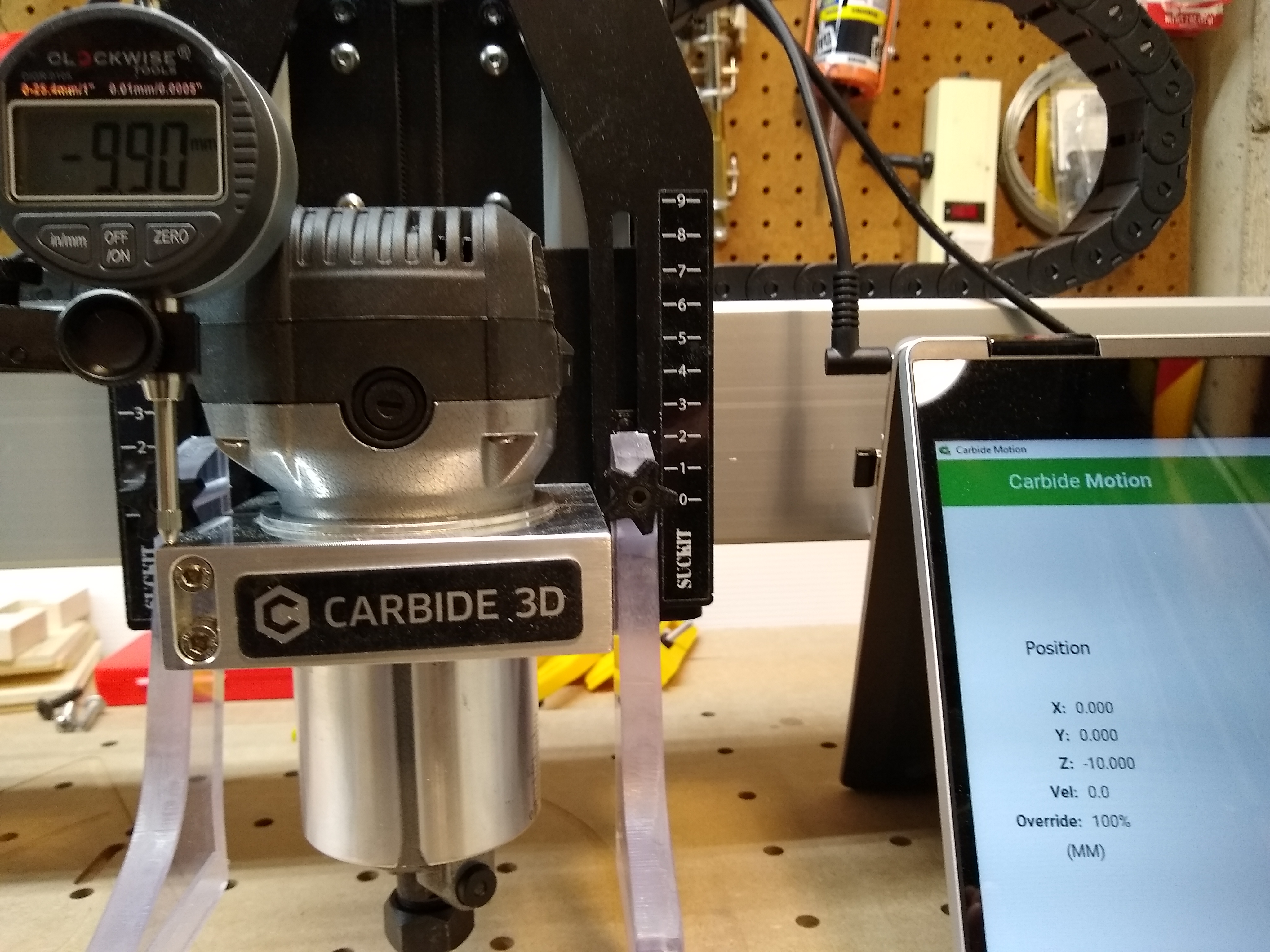
Dial gauge has arrived, with a hefty magnetic base. Clamped a piece of steel to bed, locked magnet onto it so I have a good stable base to measure from.

Zeroed at machine centre, half way through Z travel.

A single step at 1mm jog gives 1mm up, 0.85-0.87mm down. If down was the last direction, 1mm down and 0.85-0.87 up. The same circa 0.15mm backlash is there.

Using 0.25mm steps, a single jog gives 0.25mm up, 0.1 down. If down was the last direction, 0.25mm down and 0.1 up. The same .15 error.

Using 0.025mm steps, a single jog gives 0.025mm up, nothing down until the steps add up to more than 0.15mm. The same true of the reverse directions.

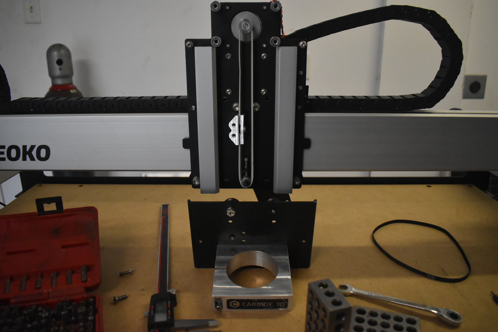
I removed the stepper pulley (which was tight), checked it for wear/ovality of hole etc., nothing. Re-fitted it and repeated the above tests with the same outcome.

I looked for movement in the X or Z carriage, vertically or trapezoidal, nothing. Checked pulley rotation for each commanded step, and it does appear to be moving as-per the jog commands.

So the only remaining component that has any slack potential is the belt. Re-tensioned it, but no change.

I have ordered a replacement belt GT2/6mm/2mm/522mm and whilst at it got a steel core equivalent (which is open, not a loop, so will have to think how to solidly joint it).

Given how fantastic this machine is, it is shame to still be wrestling with this backlash issue…

Open loop Z modification. Up to 9mm fits with correct pulley changes and spacers.

5 Likes

Congtats, that’s a good solid set of measurements.

On the downside, the lost motion is more than the measurements I get from the X axis on my XXL where a somewhat longer belt is in play.

I remain unconvinced that additional belt tension helps backlash at all, in fact if I’m right about the behaviour it may make things worse for lost motion. Setting the belt tension to achieve the expected 40 steps per mm (or whatever calibration value is in use) may well be useful however and steps per mm equivalent tensions on the two Y belts would seem to be essential to maintaining a square machine across the travel distance.

I’ve got one of the Gates GT3 belts on it’s way to me which I plan to compare with the kevlar cored belts for extension under load, I’ll also be doing a (similar to yours) set of measurements of the lost motion and where it occurs, for me that’s X and Y though as I have the HDZ.

It’s easier to see the belt stretch causing the backlash on the X axis as you can see the belt moving relative to the extrusion at the Z carriage but not the clips, it would be much harder to see this on the Z axis.

Apologies if you’ve already checked this, but is there any slop over the fixed pulley on the back of the Z carriage plate?

Movement on the static (tensioner) Z pulley is harder to measure, but I can’t detect any. It tends anyway to be under a fair bit of tension, so notchiness or ovality are the only likely factors. Can’t see or measure any…

Interesting Z-anchor mod, Vince. I think this is likely the way I will go as otherwise I am playing with an unproven jointing technique and may be introducing other variables unwittingly.

1 Like

After reading your issues, I thought I should check out my machine. Here’s what I am seeing:

Machine: Shapeoko3 XL with the original belt driven Z axis. (Purchased Nov 2019) All steel core belts.

Z Measurement Averages: 10 mm commanded = 9.90 mm movement. Lash is about .05 mm and equal in both directions.

Y Measurement Averages: 10 mm commanded = 9.98 mm movement. Lash is about .05 mm and equal in both directions.

X Measurement Averages: 10 mm commanded = 9.95 mm movement. Lash is about .08 mm and equal in both directions.

So the good thing is that I end up at the same zero spot pretty consistently (within .02 mm.) I have noticed that cutouts needed some extra depth. I always thought it was my stock measurements being off. Maybe not. Overall I am satisfied with what I am seeing on my machine although I think I’ll play with the Z steps per mm setting to see if it helps.

Steve

4 Likes

Interesting benchmark, Steve. It does suggest that I am seeing something out of the norm.
Tried using G commands to move the Z-Axis (to remove any potential for bugs etc in the Jog button code in Motion), so G21G01Z40F100 (If I have remembered what I used correctly) and see the exact same issue as originally described.
So the variables that (to my mind) remain: Belt ‘slack’ (not convinced, but still experimenting), VMotion (Apple V513), or the on-machine GRBL controller/driver (the latest PCB model, not sure about code version)

It does seem that you are seeing something different from everyone else. I also think that I have bumped into the max resolution of my Dial Indicator. I think ± 0.02 mm is about as much as I can reliably measure.

I am using CM 513 on Windows.

So ??? My only thought is make sure that your z axis V wheels are not too tight. (or too loose)

.02 mm is about what you should expect. at 40 steps/mm -> 1 step = .025 mm.

3 Likes

The jog button is a bit sketchy, particularly with the press and hold functionality. Strongly recommend using the MDI interface to command exactly what you want.

With everything on the carriage (router mounted, the whole deal) any nod that can be felt moving it by hand? I see you’ve already tried this in other directions. Are the wheels in good shape on both the x rail and the internal sliders? If not, they can cause some nod-like issues by not holding things totally vertical.

Have you checked the X to Y wheels? Any rock or looseness here will show up in the Z axis as well. Took me checking things for a few hours once before I found a broken wheel on the Y axis was causing what I thought was isolated somewhere in the Z axis. Learn from my fail :slight_smile:

There’s definitely some sort of mechanical issue here somewhere, I don’t think this is software or electronic.

Just going through these measurements again, trying G-commands and Jog, and got the same outcome. Re-tensioned all the vee wheels to ‘just holding’ on X, Y and Z. Nothing damaged, nothing unusual. Still no change in outcome.
Then I tried tensioning the Z vee belt by pushing against it whilst jogging (a bit tricky, but I kinda got the feel for holding constant pressure in the end) and got NO BACKLASH. Stopped pressing, and the backlash is still gone (down to circa 0.02mm). Think I need to double-check that the tensioner roller is not sticking once tightened, as pushing the belt might have forced ‘equalising movement’ if so. What is curious is that ‘pinging’ either side of the Z vee belt gives a different sound - the side anchored in the slide is taut, the long side is less so. I would have guessed equal tension, but I suppose the slide is ‘hung’ from the stepper pulley, so perhaps some imbalance is to be expected.
I need to start over from cold tomorrow (it’s getting late here, UK BST time) and see if I get the same results. If it is still good, the question becomes - how did it get imbalanced into backlash in the first place, and what triggers it? Questions, questions…

5 Likes

Replacement steel-cored belt has arrived, and I have made (not as elegantly) an aluminium clamp similar to Vince’s - replacing the static pulley and two posts of the original design. It’s all using the existing holes and geometry, so it can go back to standard if needs be.
Checking for backlash shows that the original 0.15mm has gone, now more like 0.02mm.
I need to establish 40 steps/mm = 1mm travelled belt tension, and go over my measurements again, but initial feeling is that this is definitely an improvement :slight_smile:

8 Likes

This topic was automatically closed 30 days after the last reply. New replies are no longer allowed.