One thing I had to decide early on was where the cut line goes.
In a lot of files I’ve seen, the outline you actually want cut is just another path mixed in with the artwork. It looks fine on screen, but whoever runs the job has to find it, pick it out from everything else and set it up by hand.
So in CEIR Vectorizer the cut line comes out on its own spot colour layer, named CutContour by default, or whatever name your workflow expects. The cutter or the print shop can find it without anyone hunting through the paths.
That idea came from print and vinyl work, though. The replies on my last two posts here about open paths and centerline traces showed me CNC files have their own habits, and I still have a lot to learn about them.
When you bring a traced file into Carbide Create, how would you want the cut paths kept apart from the rest, and what would save you the most cleanup?
If I have a particularly complex design with a lot of overlapping vectors, or just a lot of vectors, multiple layers, etc… I will organize things into layers to make the CAM programming easier.
If it’s relatively simple, I don’t bother.
However, I am Design & Manufacturing in my shop. If you’re involving a 3rd party then following their desired standard will make life much easier. Or at least some system of organization that makes it obvious what’s going on.
I will just note that Carbide Create adding support for importing Layers from a DXF has been transformative in my own work/projects — my recommendation would be to allow the user to assign different elements/operations to different layers which can then be associated w/ a suitable toolpath by the user, possibly in a pre-made template file.
Thanks Will, that’s a useful suggestion. Letting people put elements on their own layers so each one maps to a toolpath, maybe from a ready-made template, is a clear idea. I’ve noted it.
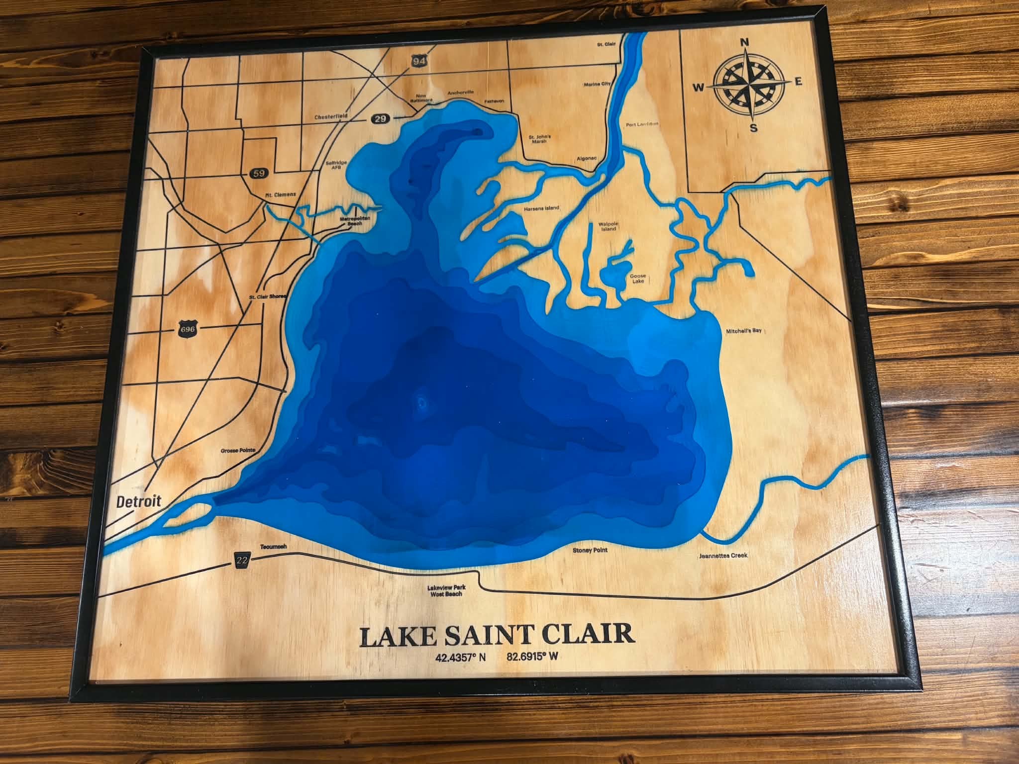
I used a combination of strategies on this one. I divided the lake depths into layers, and then sorted the roads, symbols & small text into layers as well.
Anything that using different tools, operation types, or machining strategies.
Assembly & job sequence could also be a factor. If I were going to cut one lake level, paint it, then cut the next level, and so on…
I also have construction or guide geometry on some parts that if on a separate layer can be turned off to just the final product. boundaries for 3D operations that aren’t part of the final design, etc…
That Lake St. Clair map shows it well: cutting one depth, painting it, then cutting the next only works if each level is already sitting on its own layer. The guide geometry point is new to me. When the artwork starts life as a picture there’s no construction geometry at all, so everything lands in one pile and has to be pulled apart by hand. In the tool I’m building, outside cuts, inside cuts and engraves come out on separate layers, but job order and anything like guide lines are still up to whoever sets up the job.