I have tried the procedure in the documentation, but I have some questions about how this procedure is supposed to work and there seems to be a couple of mistakes in it. I cut a set of squares to measure. This is all about setting the $100 and $101 values. The way I see it, you would only get the spot on dimensions only if the cut is about this same length as the length you pick to calibrate to.
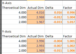
So If I get a 5" square to be right on, as the square get smaller, they get smaller than desired. Example: A 5.000 inch square measures within a .001 or 2 of perfect. By the time the square is 1 inch, it is ~0.020 smaller than expected (or .980). Well, that what I get for the X-axis on my SO3.
Does anyone have any comment on my test results, am I expecting accuracy not deliverable?
Thanks for the response, the links were interesting. However, I know my runout is quite small, that was measured.
The problem is the Belt Stretch procedure. Here are 3 points:
The $100/$101/$102 default values are 40 not 20. If didn’t realize that at first and got half size cuts!
The formula is wrong. If your system cuts long (as shown in the procedure), the $100 value should be made less not greater than the default.
I find that the corrected value work great for parts about the size of the calibration test. But dimensions significantly larger or smaller creep off the desired dimensions. This really is the focus of my question.
The belts are really new. I honestly don’t think it’s a belt issue. But of course stronger belts would better in any case.
I have worked around the issue this way:
I do my $100 and $101 correction using the part size I need to be very accurate. For me, I needed 2" circles to be spot on. I did do 2 iterations and ended up with X and Y being within 0.001 inch of the target value. GREAT, I made my parts.
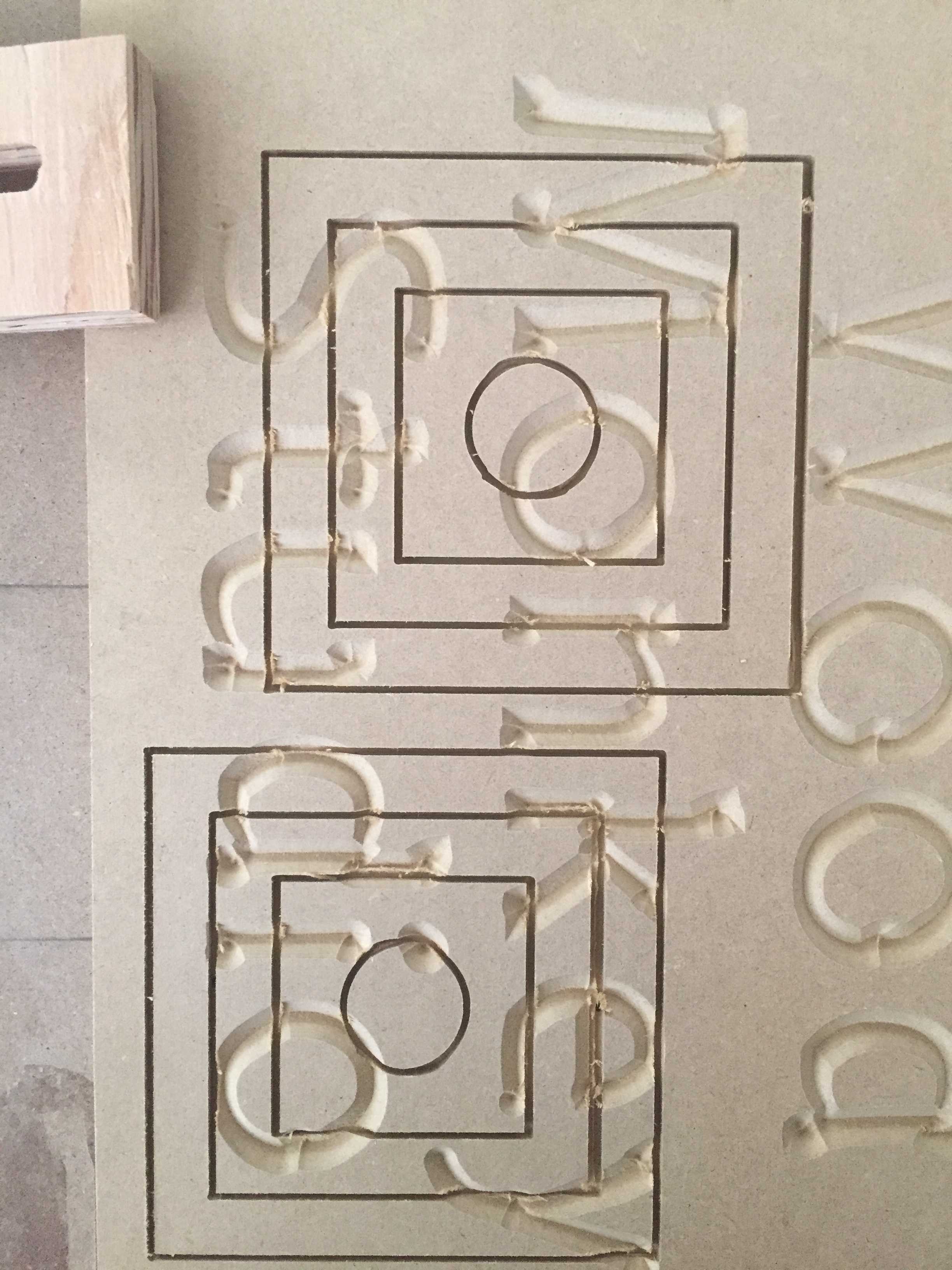
I seem to be having this same issue. I have been cutting test pattern after test pattern and feel like I am just chasing my tail. I have cut 3 concentric squares and one circle. My current X-factor is 41.476 and Y is 40.307. In the last test case, the large square measures 4.046 (in X), next one is 3.008, next one is 1.977 and circle is 0.938. As you can see, it deviates both larger AND smaller…so what the heck do I do about that?! Plus, these are significant deviations, not just a few thou here and there, which I could live with.
I am using a small bit, 1/8" shank and .058" cutting diameter. Am I to attribute this to tool deflection? I am going slow, 40 ipm, 30 and 20 (all different to see if that makes a difference). Belts are as tight as I can get them without resorting to a block and tackle I have cut this in both virgin material and across previous tests with essentially the same outcome.
I tried this again using a 1/4" flat endmill with largely the same results…some too big, some too small all in the same run. These are simple files I created within Carbide Create and the geometry is good. Frustrating to say the least when I see many reports of good accuracy. Hell I’d be happy with +/- 0.01 right now but not seeing that at all.
I am not sure how to tell. I have a 4", 3" and 2" square along with a 1" circle. I can see the GCode, but not sure how to interpret it to verify accurate positions. I assume it’s all in MM, which is easy enough to convert, I know, but I am just not sure where to begin and end with the calculations. Further, don’t you have to factor in the X and Y axis step factors? Here is the code:
No I mean calibrating your machine to make sure it moves 100 mm when you tell it to move 100 mm using a yardstick or other accurate linear measurement.
Here is a decent video. Just remember this is for the XCarve so you will have to use a the MDI commands instead of the Machine Inspector.
Since I have been through this. Let me re-comment on it.
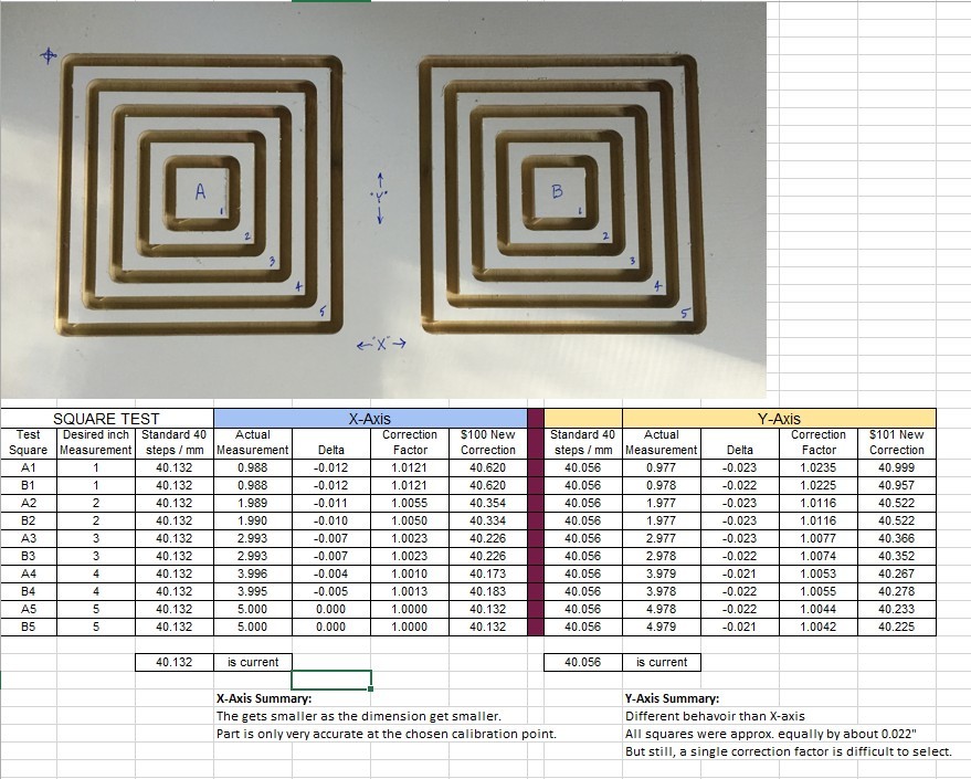
If you take away any offset corrections you have made and start from scratch. Then cut a 5 inch square and precisely measure it. Do the math and enter the corrections. Then cut another 5 inch square. You will find it comes out pretty close to perfect. However, (correct me if I am wrong), if you cut a 3 inch square you will find it to be slightly smaller, likewise a larger square slightly larger.
Now - I know I do not have a runout issue (a wobbling bit), I checked that by measuring the inside and outside dim’s of the groove cut. But you also have to make sure you have the new Z-Plate to eliminate that potential issue. But the Z-Plate should not affect the X-axis.
I am now in a don’t care situation because I just calibrate around what I need to be PRECISE. So if I REALLY need something exactly around the 3 inch area, I would drive my calibration around that. The data I took on my system fell on deaf ears. If you really look in detail about how this X,Y correction is formulated, you will find it works this way. It says that “I need to go a little further or not quite as far for X inches”. But then assumes that same little delta would be the same for any distance. I find this to be not true.
The belt stretch calibration technique adjusts the machine’s steps per mm. Ideally this would be “linear”, that is, consistent across the entire range of motion of the machine’s axes. If it isn’t then that means the machine is nonlinear: the steps per mm varies throughout the range of motion of the machine, so calibrating in one place or over one distance will give you different results from other places and distances.
I am not being overly precise in my calibration, but when I calibrated at 3 inches (by milling a block that size and measuring with calipers) I got very close to the same result as at 2 feet (by moving a v-bit along a secured metal square).
Technically, every system is nonlinear: they are just designed to be linear within specifications. (Back in the stone age I paid the bills as a test engineer - in mixed signal electronics not mechanical systems). It isn’t even exactly clear to me (as a CNC noob) what the linearity spec of a CNC machine would look like, but these hobby machines don’t have many specs in the first place: they do as well as they do, and if that works for your application then great.
It is always a good idea to calibrate to the range that is important to you, so that’s great advice by DJ_Valenski.
Thanks, I will give that a try. However, if this is the behavior that is to be expected, meaning it is only accurate in a very small range and outside of that it is crap, well this is not the machine for me.
@ApolloCrowe
Is this the type of accuracy and behavior that is to be expected of these routers?
I think you may be misled. I get great accuracy out of mine. If you expect .001" accuracy out of a hobby machine you will be disappointed. But you should be getting pretty close. Mine is normally within .003 - .005 across the entire 34" of the machine span on my Shapeoko 3XXL. Even more important it is always consistent from cut to cut.
That level of accuracy is more than acceptable. I am willing to live with +/- 0.010 but if I can get to where you are, then all the better! I will try as suggested, but I am currently at a loss as to why I am seeing such inconsistency from cut to cut. This is the result of my last set of tests (one of many).
 I have cut this in both virgin material and across previous tests with essentially the same outcome.