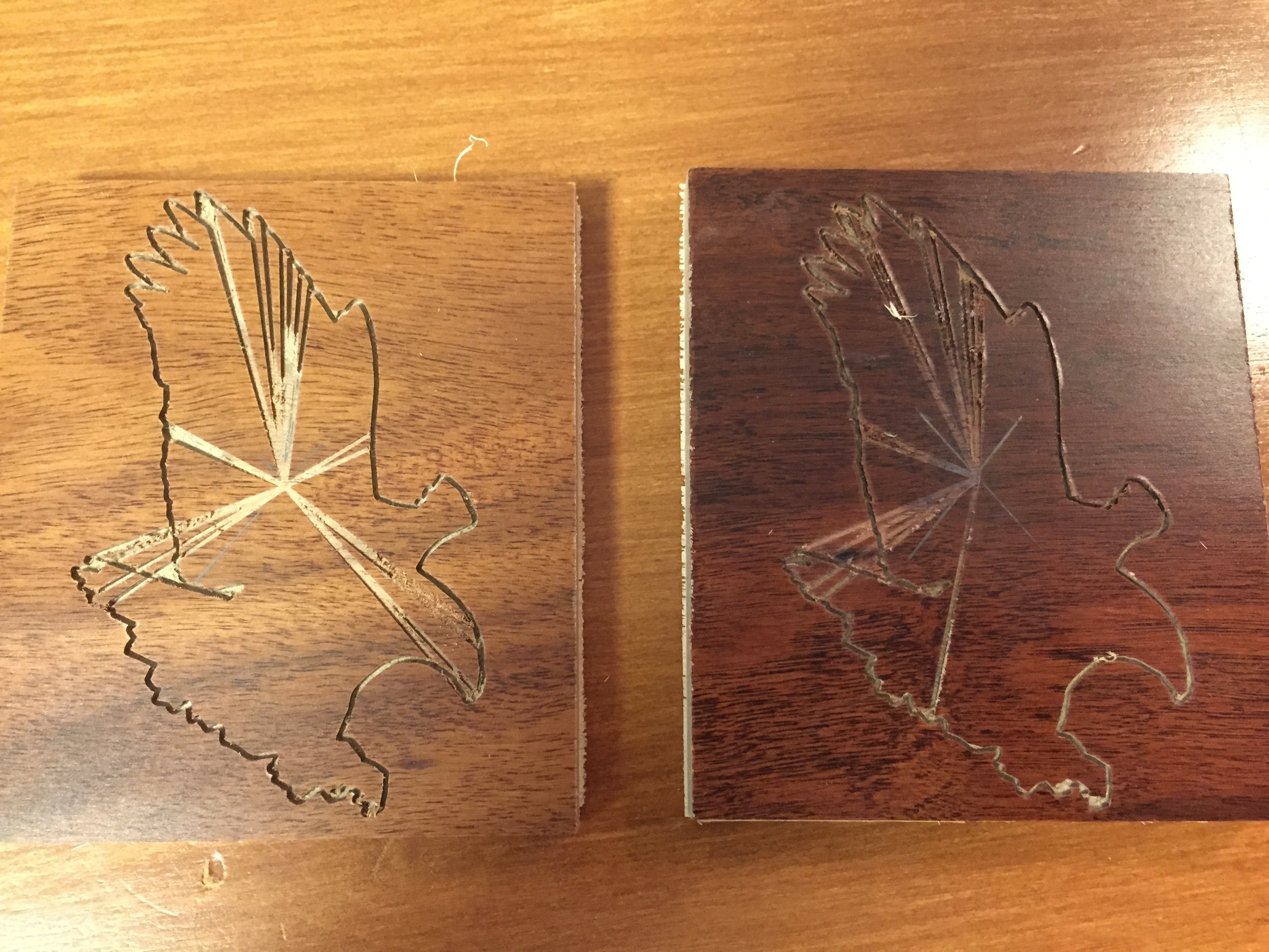
When making a cut of the outline of an eagle I am getting extra unwanted cut lines across the body of the eagle starting from the zero point in the top center of the stock. I m not sure what causes them or what to look at to fix it.
I loaded a DXF file on an Eagle into Meshcam then scaled it 40% to fit on a
piece of stock I had. The outline of the eagle cut nicely, but there were extra lines
across the body of the Eagle that should not be there.
The extra lines all seem to start from the zero position which was in the top center of the stock. I then raised my retract height and tried another cut. I got a very similar result, but a couple of lines across the body of the eagle were not there in the second cut. The results are shown in the photo below
Has anyone seen this type of thing before? What should I look at to fix it and just get the outline of the eagle cut, without the scratches starting from the zero position in the center of the stock?
Steve, could you zip and attach the gcode for this job? I’ll take a look at it in CutViewer. CV traces out the cuts as they occur instead of doing the whole calculation and then showing the results, so it sometimes gives more insight into a problem or behavior.
Lines radiating out from the origin sounds vaguely familiar from years ago, but I can’t place the memory right now. It will probably come to me just as I’m falling asleep tonight…
I zipped the file then changed the extension to ‘pdf’ because
the board will not let me attach a zip file or an nc file. Download the
file then change the extension from pdf to zip and it should work.
If not email me directly and I will attach the zip file to an email.
Let me know what your simulator shows.
Are there any other setup parameters I could have gotten wrong to cause this?
There is one spot at the front just left of center where there are no waterline passes but the pencil finishing, but that would not cause the radial lines from the origin.
They are not in the gcode, and therefore not caused by your parameter settings (which look very reasonable), so they must be some artifact of Carbide Motion. I’ll run the gcode tomorrow (air cutting) and see if I see anything weird.
Your parameters overall look fine. I’d change the tolerance to .0001" which should help with the fiddly contours; notice at the tip of the beak the waterline and pencil are slightly different shapes. They use different algorithms (the pencil is actually a full 3D calculation) so finer tolerance will result in them tracking closer.
I’d also make the pencil finishing the same plunge and feed as the waterline. In this 2.5D case, pencil is effectively just the last waterline pass, and potentially could have a full waterline stepdown so there isn’t a real justification in running it faster.
But those are nothing that would cause the radial lines, just things I consider “good form”
Looking at the code in OpenSCAM, it did not like it, only giving a single part of the trace, so I looked at the file.
Many Lines of “XnanYnanZnan” in the file. I’m guessing that’s what it’s not liking. Looks like a bug in meshcam for outputting those.
James, you beat me half an hour, and you are spot on! I was just about to post the same thing.
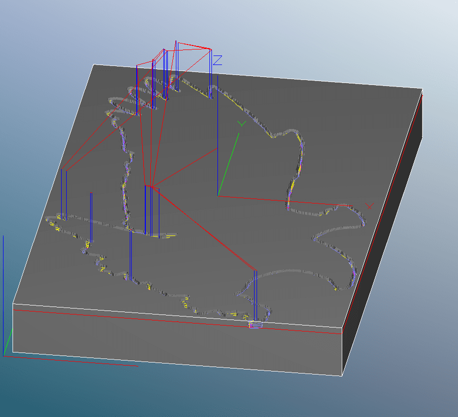
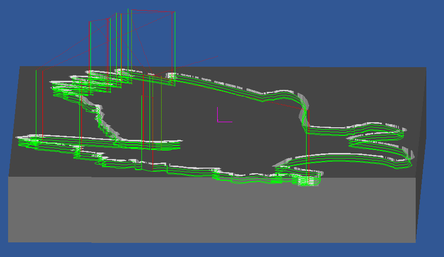
Air-cutting the file produed the anamolous moves to X0Y0Z0 that seem to be caused by the XnanYnanZnan lines, of which there are 16. Removing the lines eliminated the anamolous moves.
@Steve, I see you have arc fitting enabled. Look at your Carbide3D-MM.con in the posts folder and see if the formatting lines for arc moves (the bolded lines below) are commented out (with leading semicolons). Edit: I have fixed the copy below by removing the offending semicolons:
; MeshCAM config
; This config is the Carbide3D Nomad 883
; http://www.carbide3d.com
;
DESCRIPTION = “Carbide3D-MM(*.nc)”
FILE_EXTENSION = “nc”
UNITS=MM
;Feeds
FORMAT = [F|#|F|1.1]
;Moves FORMAT = [I|@|I|1.3] FORMAT = [J|@|J|1.3]
FORMAT = [X|#|X|1.3]
FORMAT = [Y|#|Y|1.3]
FORMAT = [Z|#|Z|1.3]
FORMAT = [R|#|A|1.3]
;
;
COMMENT_START = “(”
COMMENT_END = “)”
;
START = “%”
START = “(FILENAME: [FILENAME])”
;;the following sets the stock for CutViewer
START = “([CUTVIEWERSTOCK])”
START = “G21”
START = “G90”
;
TOOLCHANGE = “([CUTVIEWERTOOL])”
TOOLCHANGE = “M6 [T]”
TOOLCHANGE = “M3 [S]”
;
RAPID_RATE_MOVE = “G0[Y][Z]”
;
FIRST_FEED_RATE_MOVE = “G1[R][Y][Z][F]”
FEED_RATE_MOVE = “[R][Y][Z]”
; FIRST_CW_ARC_MOVE = “G2[X][Y][I][J][F]” CW_ARC_MOVE = “G2[X][Y][I][J]”
; FIRST_CCW_ARC_MOVE = “G3[X][Y][I][J][F]” CCW_ARC_MOVE = “G3[X][Y][I][J]”
;
;
END = “M5”
END = “M30”
END = “(END)”
END = “(OF PROGRAM)”
If so, uncomment them as per above. They were commented out in my copy of the MM post, but not the inch post… That is a possible source of the anamolous lines.
I found the posts folder by showing the contents of the meshcam program in the applications folder (I am on an iMac). There are two carbide3D files. One is carbide3D-Inch.com and the other is carbide3D-MM.com. I have listed them both below, should I make changes? Both files have the same format commands commented out. The inch file has FORMAT = [X|#|X|1.4] and the MM file has FORMAT = [X|#|X|1.3]
the difference being 1.4 in the inch file and 1.3 in the mm file. In the middle of the files the inch one uses START = “G20” and the MM file uses START = “G21”
I have arc-fitting enabled but do not clearly understand what it does. When should I be using arc fitting and when should I not use it?
Thanks for looking into this. It not only helps to resolve the issue, but following along what you are doing I am learning a lot about how to debug gcode and more of how meshcam works. This is really helpful.
carbide3D-Inch.com follows
; MeshCAM config
; This config is the Carbide 3D Nomad 883
; http://www.carbide3d.com
;
;
DESCRIPTION = "Carbide3D-Inch(*.nc)"
FILE_EXTENSION = "nc"
UNITS=INCH
;Feeds
FORMAT = [F|#|F|1.1]
;Moves
;FORMAT = [I|@|I|1.4]
;FORMAT = [J|@|J|1.4]
FORMAT = [X|#|X|1.4]
FORMAT = [Y|#|Y|1.4]
FORMAT = [Z|#|Z|1.4]
FORMAT = [R|#|A|1.4]
;
;
COMMENT_START = "("
COMMENT_END = “)”
;
START = "%"
START = “(FILENAME: [FILENAME])”
;;the following sets the stock for CutViewer
START = "([CUTVIEWERSTOCK])"
START = "G20"
START = “G90”
;
TOOLCHANGE = "([CUTVIEWERTOOL])"
TOOLCHANGE = "M6 [T]"
TOOLCHANGE = “M3 [S]”
;
RAPID_RATE_MOVE = “G0[X][Y][Z]”
;
FIRST_FEED_RATE_MOVE = "G1[R][X][Y][Z][F]"
FEED_RATE_MOVE = “[R][X][Y][Z]”
;
;FIRST_CW_ARC_MOVE = “G2[X][Y][I][J][F]”
;CW_ARC_MOVE = “G2[X][Y][I][J]”
;
;FIRST_CCW_ARC_MOVE = “G3[X][Y][I][J][F]”
;CCW_ARC_MOVE = “G3[X][Y][I][J]”
;
;
END = "M5"
END = "M30"
END = "(END)"
END = “(OF PROGRAM)”
@3dsteve, the G20 calls for inch coordinates and the G21 calls for mm coordinates. The 1.3 in the mm format statement calls for 3 decimal place coordinates and the 1.4 in the inch format statement calls for 4 decimal place coordinates.
There is a good explanation of the post file structure in MeshCAM Help | Help | Post Processor.
When you have arc fitting enabled, MeshCAM will replace strings of little straight moves with an arc when it can stay in the calculation tolerance doing so. It’s mostly useful when you have an STL that has obviously round features, less so for an “artsy” contour like your eagle. But arcs give very smooth cutter movement where they’re available so they’re a good thing to use. It doesn’t hurt to keep that enabled full-time becuase there’s no downside (other than the post processor not being configured for them…) Arcs are only defined for waterline moves in the X-Y plane. Roughing doesn’t use arcs (it uses a different calculation algorithm) and pencil, being a 3D calculation, also can’t use arcs.
Ah, we’re typing at the same time. I had just edited my post to say there are no downsides for keeping arc fitting turned on all the time, so go ahead and uncomment those formatting lines and keep arc fitting turned on (as I just edited above )
Yes, exactly. I’m sorry I wasn’t more explicit in describing that. You can comment out and uncomment lines by adding or removing the leading semicolon.


 )
)