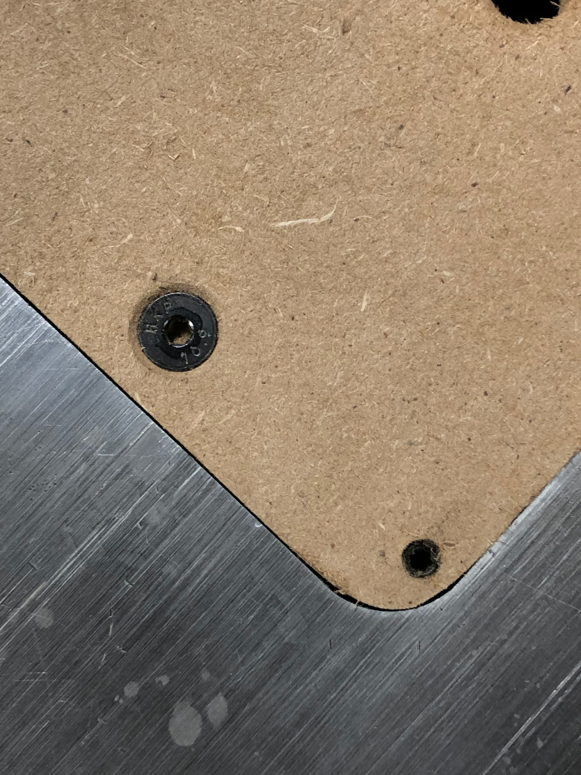
The problem is that the bottom of this plate sits on a surface, and the screw goes into that surface.
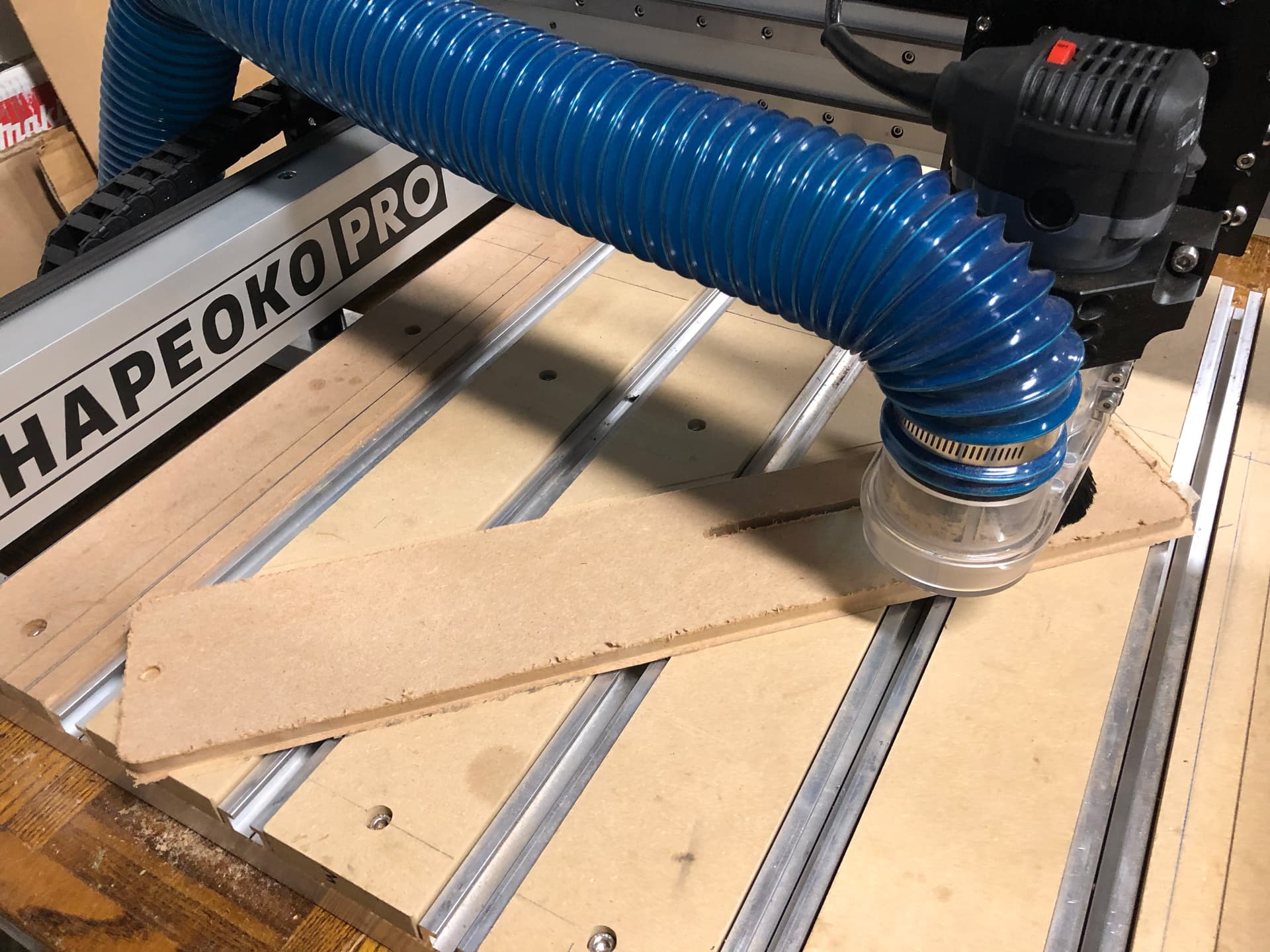
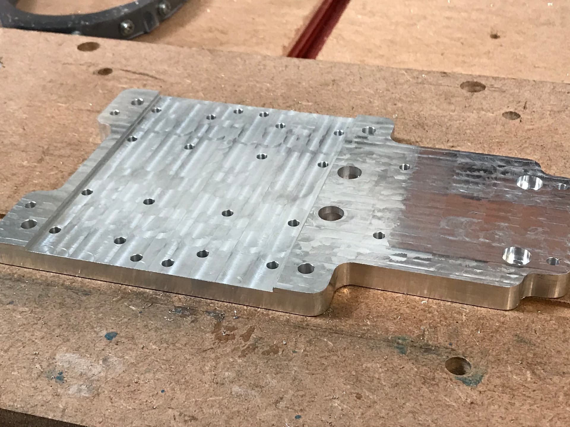
Got a prototype in MDF cut and installed. I had to chisel out underneath since even at the lowest position, the top of the blade was hitting the bottom of the insert. I cut some dust collection holes by hand, but once I decide on the right pattern I’ll build those into the model of course. I got the insert width just right, but I’m a tad long on the length, so I need to adjust the model to avoid touching up on the disk sander.
I ended up using the “Hole” operation in Fusion 360 for all the holes. Worked out well. Liam, I couldn’t reproduce what you did with the counterbore. I ended up cutting some of it away with the ¼" bit and then doing a “Drill” toolpath with the 90º V bit. That’s fine in MDF and probably the plastics - not sure about aluminum.
I didn’t need to tap threads for MDF, but I do have a tap and will try it out by hand with the plastics when that material arrives next week. Still debating whether I’ll need a milling pass from underneath - thinking I want a thicker plate for rigidity, but that means cutting away where it rests on the rabbets as well as clearing a couple areas for some mechanisms about 10mm below the surface under the plate.
Here’s a video of it in action: InsertInAction on Vimeo
Sorry for the iPhone jelly video effect.
And some photos:
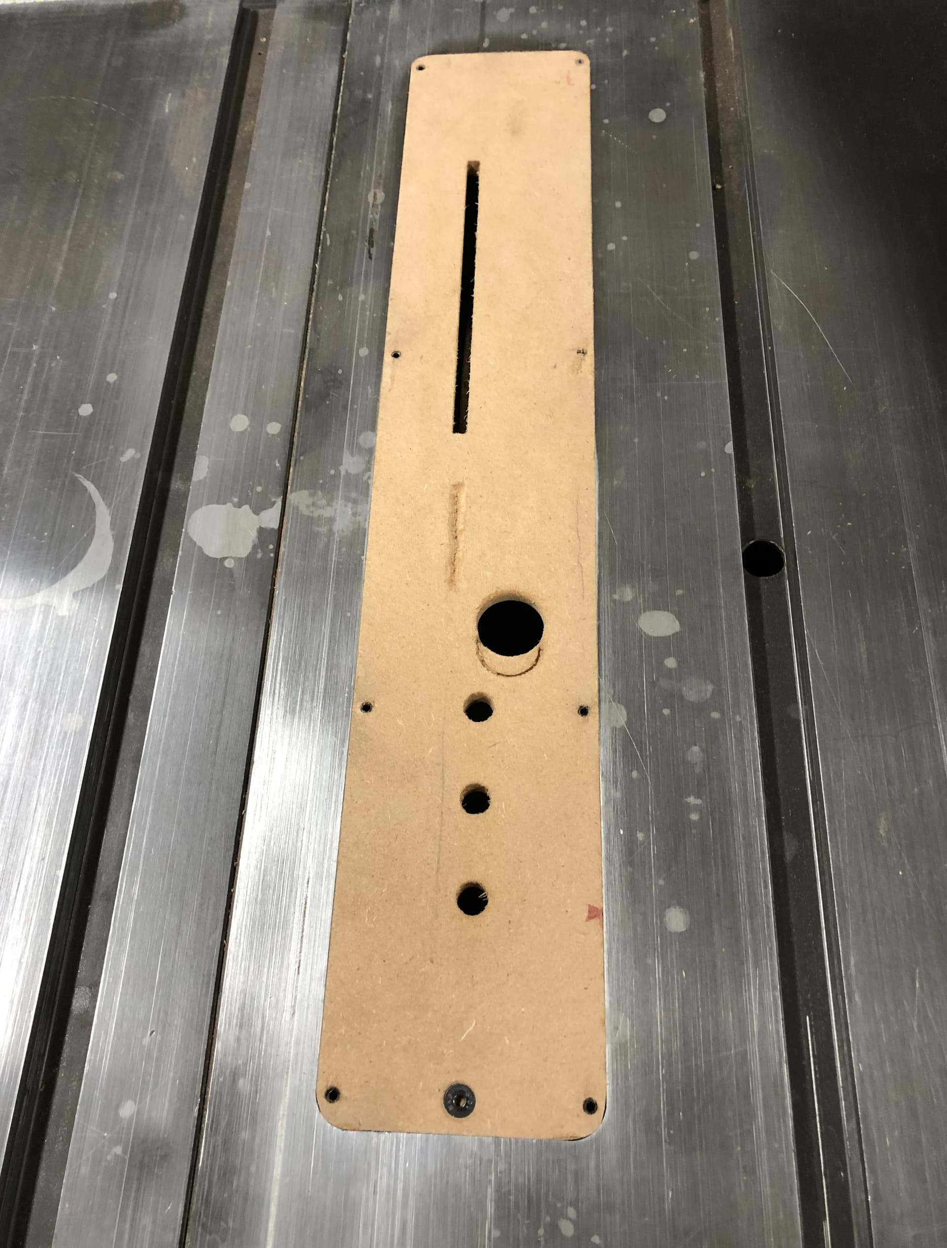

Oh, and note that I was able to cut two ~7.9mm thick insert plates out of single ¾"-ish piece of MDF. And by doing that the two piece had some warp to them. Which is perfect for my needs!
Attaching the Fusion file in case anyone wants to analyze and critique.
thanks!
ThroatPlate 90Blade NoSideTaper V6.f3d.zip (455.5 KB)
1 Like
Some suggestions on the Fusion model, nothing wrong with yours but here are some other ways you could do it.
I personally, would not have modelled the threads in the holes, I think it just makes the machining harder to set up, unless you actually have a tapping attachment for the CNC. I model threads for 3D printing but just the tap drill size hole for Shapeoko.
I would leave the outer boundary cut out until last, the bigger the workpiece the easier it is to hold down, I tend to do the smaller internal features first where I have a heavier workpiece for stock. At this size and with stock this close to the body size it probably doesn’t make much difference though.
I would not have used the move to place the plate at XYZ origin in the model space, I always set the machining origin per setup, that way I’m not dependent upon a move which may become inaccurate if I change the thickness of the part or some other aspect. I see you have a separate stock body which is the basis for the origin in the CAM setup anyway, set at 45 degrees, are your parts bigger than your machine? 
The Riving Knife Slot setup -
The spindle speed of 5000RPM in that toolpath seems a bit low.
The second op with the 1/8th cutter could also be a contour with a finishing stepover to avoid having to do that helical ramp in. Not sure which is better or faster.
I might also do all of this with the 1/8th cutter to avoid the tool change.
The holes, I might use a boring op instead, once the threads are removed from the model. The hole with the chamfer top can be a gotcha here, just set the top height in the boring op to be stock top and you won’t get the scary plunge to start in the middle of the workpiece…
I’ve set up a contour toolpath using the 90 deg chamfer cutter you defined for the countersink. It’s not exactly obvious, I think it was an NYCNC YT video I learned this from.
The adaptive which does the outer contour I might break up. Adaptive isn’t really a finishing strategy and the plunge to start would be a bit “stand well clear” in metal  .
.
I might do this with a 2D contour around the outer edge first and then use a 3D contour and parallel toolpath pair to do the clip piece.
Here’s the file with the other options for toolpaths inserted.
HTH
ThroatPlate 90Blade NoSideTaper - CAM options.f3d.zip (260.7 KB)
1 Like
Thanks for all the tips and advice! Some comments:
-
I decided to cut the outer boundary first since I use the same ¼" bit to cut the riving knife slot and I wanted to use the smaller ⅛" bit to cleanup the corners of the slot and wanted to reduce bit swapping. As you pointed out, the bottom surface area is hardly changed at all by doing the outer boundary, so there’s no practical difference in ability to hold the thin stock to the spoilboard.
-
Yeah, I’m not totally happy with my machining origin, as it requires that the raw stock be pre-milled to an accurate thickness (for the front countersink and the rear protrusion). I’ll probably change that to be the same XY, but the top of the plate for Z. That also makes using the BitSetter easier.
BTW, it’s amazingly great that it works even with the stock at a 45 degree angle!
However, with zero at the top of the workpiece, how can I ensure that I won’t mill into the spoilboard, other than again milling the thickness accurately? The only option I can think of is to keep machining origin where it is and add a top surfacing operation. That way as long as the raw stock is thick enough it’ll be milled to the proper thickness and not cut into the spoilboard. Thoughts?
-
I fixed the Riving Knife Slot setup in a later version. I haven’t played with any of those other parameters yet. With MDF it’s not a problem, but I’m getting some plastic soon. Any advice on what settings I should make would be appreciated.
-
The threading thing is just a checkbox in the Hole model diagram. I left it because it made the model look more accurate, but I can easily uncheck it if you say it changes how the milling happens. I was surprised I didn’t get a warning about the threads not being milled in the Manufacture tab.
-
Looking over the Bore and other Manufacture ops you created. This is where I’m weakest with Fusion. Given what they’re doing with AI these days, you’d think Autodesk would have an AI Manufacture in which you’d input what bits you have available (it already knows what kind of machine you have) and then it would choose the right operations and order of operations, for some definition of “right.”
Thanks again - I’ve still lots to learn here.
1 Like
NP,
I have moved to a process where I Z zero off the spoilboard and surface the stock to thickness (assuming I can, so plastics, metals, hardwoods etc. but I have to take what I get with Plywood). I frequently run a surfacing job on the bowed up side first to level it, make that the ‘bottom’, do the workholding and then surface to final thickness before the job. If you have a thicknesser planer or similar that is probably a lot faster.
I now regularly cut down to the top layer of tape and no further, leaving an ‘onion skin’ attaching the part to the stock is also easy zeroed off the spoilboard.
Aha, deploy le @Julien ! He knows way more about plastics than I do.
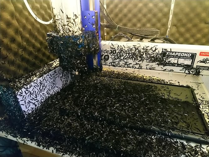
I’m about to sabotage a perfectly good Ikea chopping board for my sharpening stones, I’m feeding at 2,000mm/min and will work out the depth I can cut with manageable chip evacuation on the job. Moving fast to avoid melting is the main thing I have learned. Also, make sure your grounding is well sorted, plastic chips bring all the static, stick to everything and can cause disconnects.
Yep, I saw that, it was interesting looking at your file, I’ve got in the habit of drawing circles in sketches and extruding instead of creating cylinders or holes, it’s always good to question your unthinking habits, thanks.
It’s not so much a machining problem, just the bore toolpath will only use a circular bore so you need to lose the threads to get that option available.
Indeed, much like their generative design, I dread to think how many cloud credits it would consume though…
I think we’re all learning, that’s the fun ![]()
1 Like
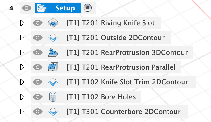
I renamed and reordered your machining operations to reduce bit swapping:
I think this will be just fine.
I can of course thickness wood/plastic stock but I’m not going to run an aluminum sheet through my thickness planer or even drum sander. I have leeway in the rear protrusion since it has a grub screw to set proper height/depth, but the front screw counterbore may need a by hand touchup if it’s not deep enough.
As you can see, I put the tool number in the filename to ensure I load the right tool. They all have “T1” by default - is there a way to change that so the prompt I get in CM would be right?
thanks, again!
1 Like
Ah,
So the tool ID is T201, I think the [T1] is the toolpath number.
What I do is right click on the toolpath and select “Add to new folder” and name that folder something like “3.175mm flat” after the tool, then put put the toolpaths with that cutter in that folder. Then a folder is one step in my machining. I post process a folder at a time to gcode for Carbide Motion and name the output things like
My Widget 1 Clearing - 6.35mm Flat - FLSBZ.nc
The 1 telling me the job order and getting alphabetic sort to work when picking files
Clearing reminds me what it’s doing
6.35mm Flat is the end mill I’m running
FLSBZ is Front Left SpoilBoard Zero (that contracted trick I picked up from somebody here, sorry, I don’t remember who)
I don’t know of a way to get Carbide Motion to know about tools by ID other than the Carbide tool IDs, I seem to recall a feature request about that. Fusion seems to assume that your mill has an ATC and knows all the tools by a 4 digit number.
If I need dimensional accuracy or a really flat finish, I surface Aluminium stock before using it, the bar stock is typically not flat and the mill face is not very clean, a quick pass with a good single flute DLC coated end mill leaves something shiny
3 Likes
Le @Julien only swears by O-flute endmills when it comes to cutting plastics.
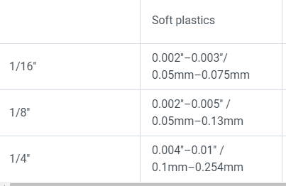
And the chipload rules below have served me well so far (depth of cut as per @Liam’s approach)
I don’t see what you are talking about
4 Likes
Where might I purchase 0-flute endmills? Examples?
thanks!
I’m a big fan of Amana O-flutes (they are somewhat pricy)
The C3D store has a two-pack for example.
Those will work great, but HDPE is forgiving and any O-flute should work really, as long as it’s reasonably sharp.
1 Like
Slight detour here. I’m looking to engrave some letters in the top of the insert plate, just for branding kicks. But, I can’t get the Engrave toolpath to work with either the 60 nor 90 degree chamfer bits. What am I doing wrong?
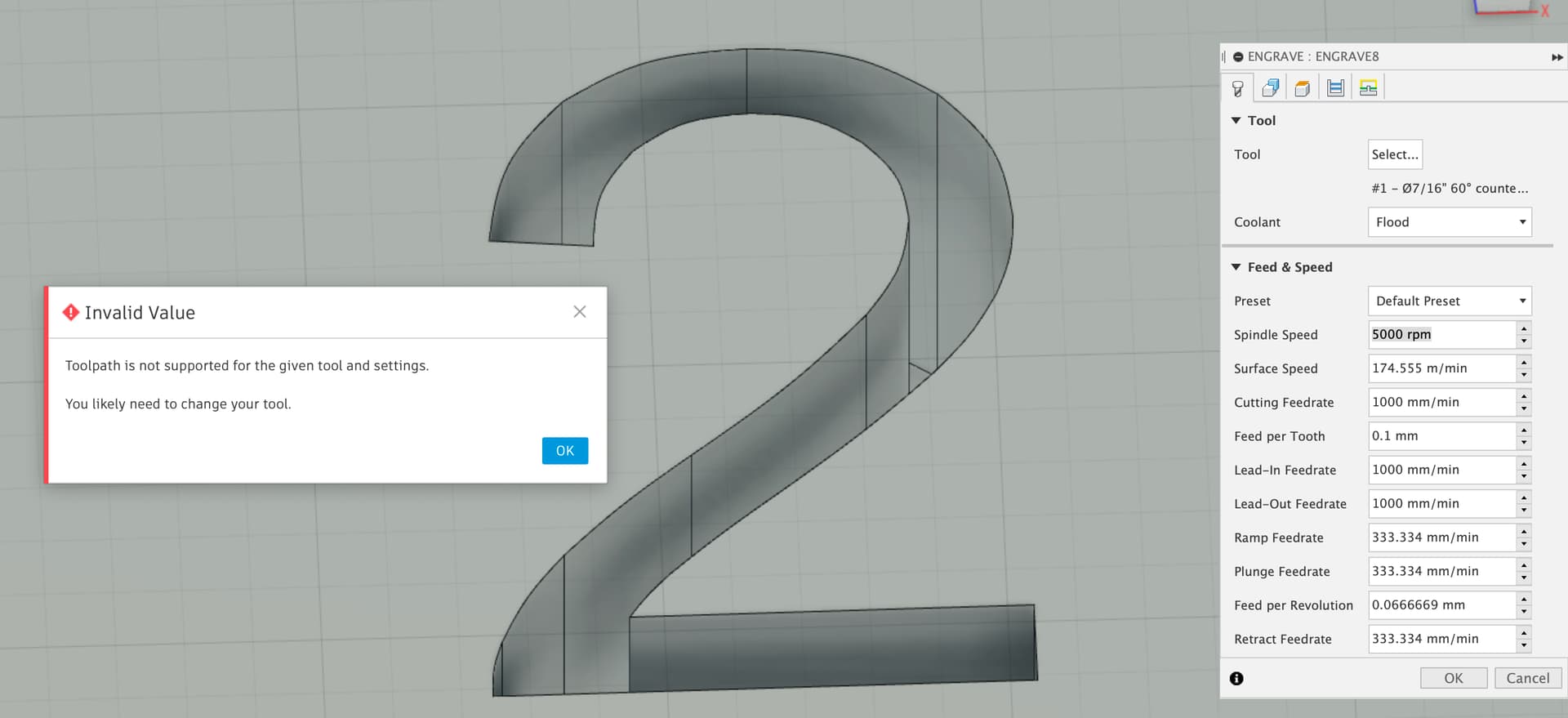

I’m using the Arial font and doing a Cut, but that shouldn’t matter since the bit depth is set by the letter width, right?
TIA
The engrave toolpaths apparently require the tool to be declared as “Engrave/Chamfer” type. I suppose you could just create a custom chamfer tool, give it the same geometry/angle, and actually your vbit instead.
1 Like
OK that worked. I first tried duplicating the tool, but then couldn’t change the type to be “Engrave/Chamfer” so I had to recreate from scratch after screen grabbing the original tool.
Challenge accepted…
I decided it was time for Ikea chopping board vs. 8mm O Flute at 22kRPM and 3,000mm/min, the chopping board lost. I did not seem to have a termite infestation after the job however?

4 Likes
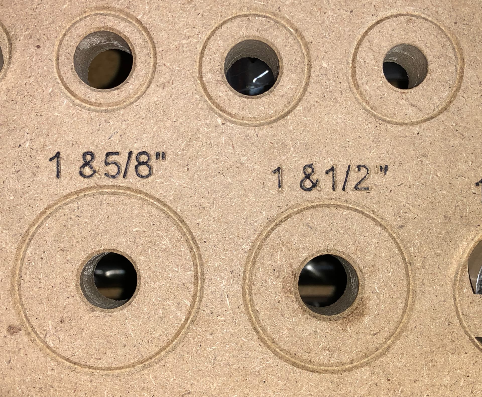
I got engraving to work and built this simple jig to hold my various Forstner bits.
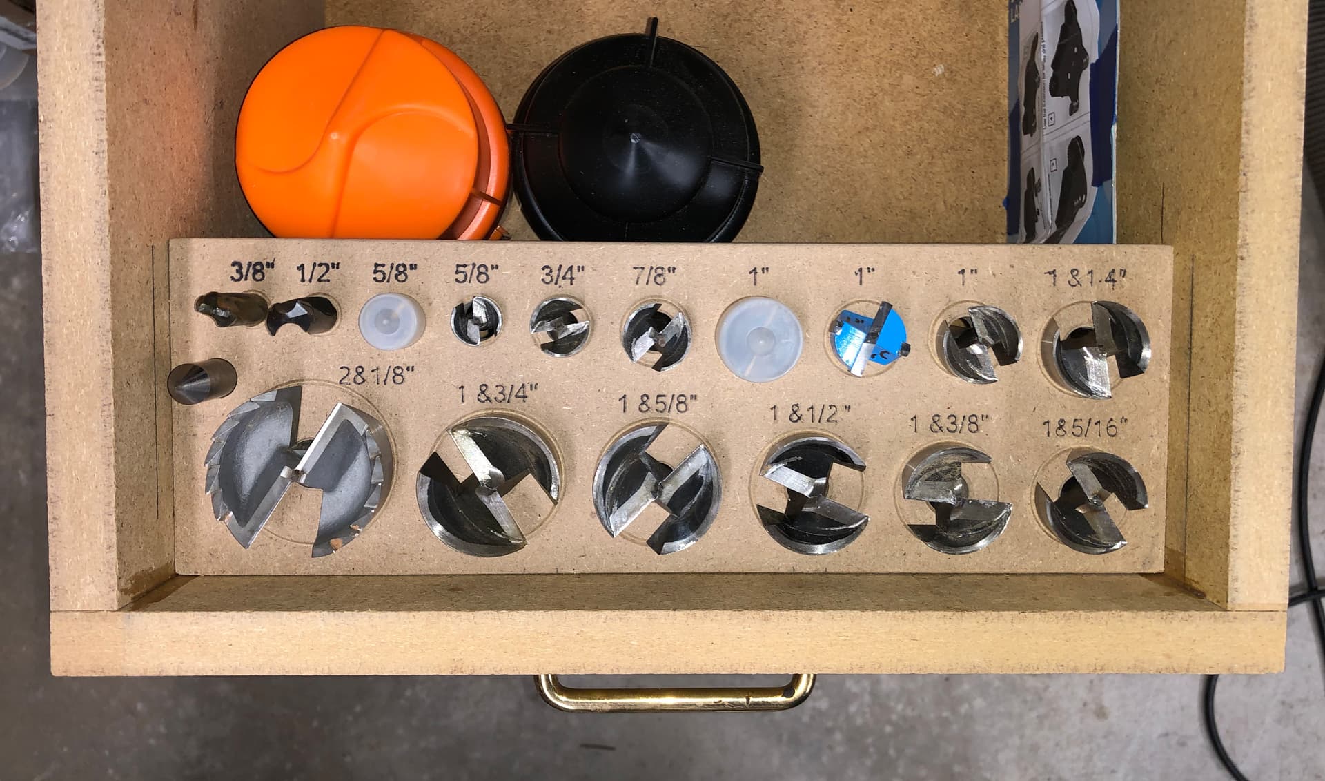
Just used a small sharpie in the lettering rather than spraying and then trimming off a top layer:
Will keep the Fusion file in case I end up buying yet another bit for some project.
3 Likes
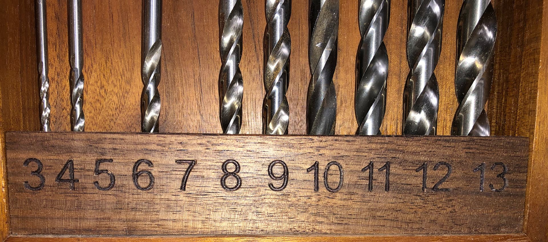
Many decades ago I bought my first real tablesaw. I built a frame for some brad point drill bits I owned as the first project to try it out. Made from walnut I got for pennies on the board foot. Today I have many more brad point drill bits, so I have a cylindrical plastic index to hold them. One supply shop was blowing out their metric drill bits, so since I’m all about metric these days I bought every bit they had that I didn’t already have (only had the 5mm, 9mm, and 10mm sizes) and so I decided to repurpose my old drill index box for the new metric bits. This meant routing out the old glued in piece of wood that had holes for the old bits. Back in the day, I used a hand-held drill with the actual bit and lots of wiggle to create the holes. Today I used the CNC (yeah!) to make holes 0.5mm bigger than the bits and spaced more accurately:
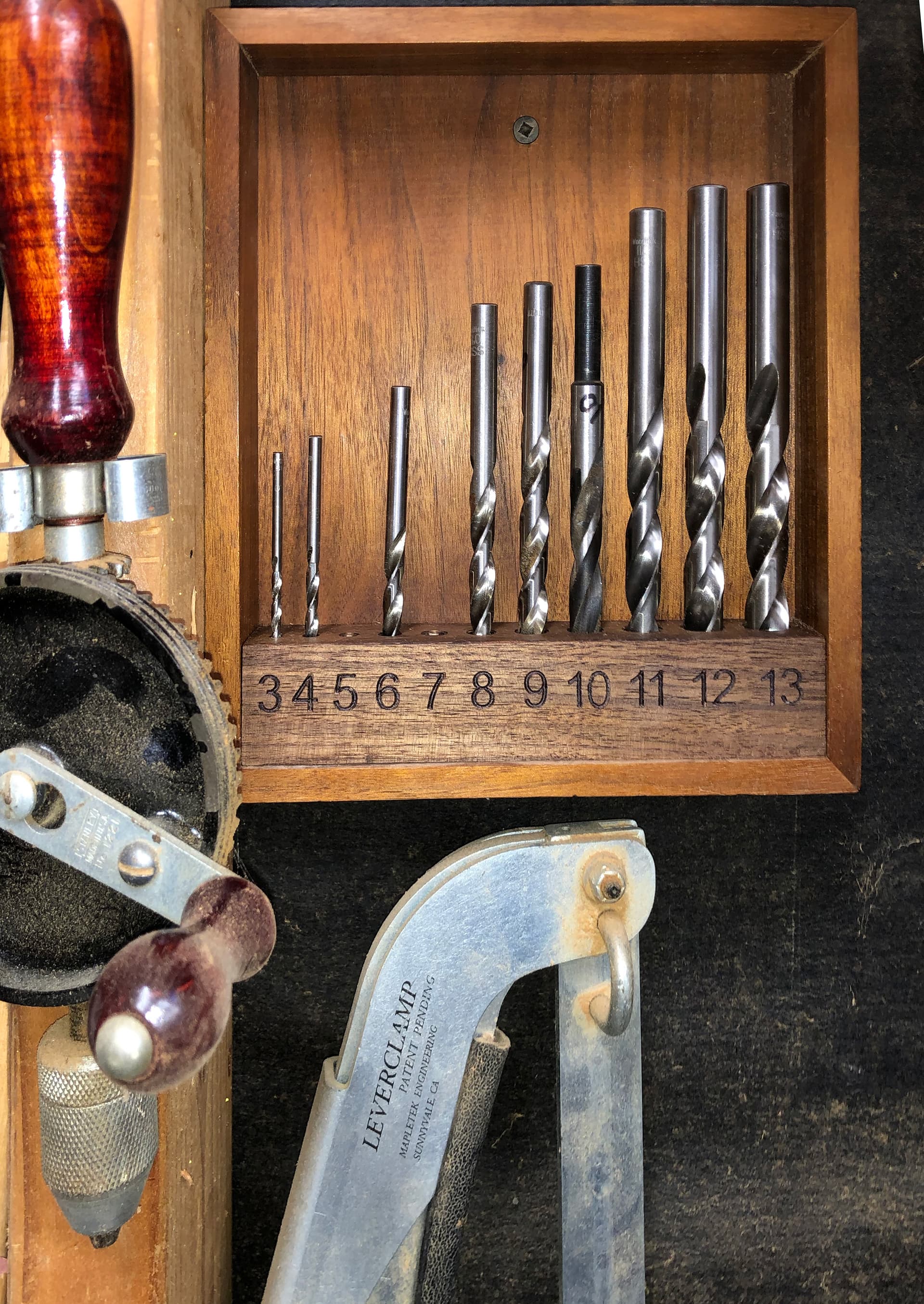
- Discovering engraving with the CNC reminds me of the first time I got one of those tape lablers. I went around making labels for everything…
And, of course, the beauty of metric here. With imperial, even going to the equivalent resolution would be: 1/8, 5/32, 3/16, 7/32, 1/4, 9/32… Yick.
Anyway, back to the throat plates. I’ve been using the MDF one I cut with some hand-drilled holes for dust collection. Now I’ll program in those holes and cut another one. Still waiting for my plastic sheets (and bits) to arrive.
1 Like
This was why traditional augur bit sets were marked by 16ths, so this set:
would have been numbered 4–16
In the same vein as this, I designed and made a throat plate for my dad for his Delta Unisaw cabinet table saw. It works awesome and threading set screws directly into MDF works well for leveling. I thought I would want to remake this in HDPE or aluminum but MDF, especially if waxed, works really well.
I’ll post my file up here later today.

3 Likes
Sorry I haven’t followed up with my progress recently, but that’s because I’ve had very little progress.
I have procured some HDPE, acrylic, and acetal copolymer sheets, as well as the bits Julien recommended. I still haven’t finalized the dust collection holes/slots.
I need a tutorial on feeds and speeds for these plastics, oriented towards Fusion360. Anyone got any pointers for me?
TIA, as usual.
If you start from the chipload ballpark I mentioned earlier, you have a starting point: choose an RPM value (let’s say 18k), pick a target chipload depending on endmill diameter (Say, 0,007" for a 1/4" endmill in HDPE), then determine feedrate like so:
Feedrate = chipload x RPM x nb of flutes.
Depth per pass = 50% of endmill diameter.
There are refinements if you are using adaptive toolpaths, but even ignoring chip thinning will work.
And if you get melting/strings: feed faster.
3 Likes