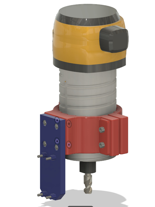
Here’s the NEJE laser mount design files if anyone else wants to go down that road.
Pic is a link:
6 Likes
@neilferreri Whats your take on this https://uk.gearbest.com/laser-module/pp_009558584217.html
I haven’t received my new Ortur Master 2 yet and I’m already looking at bigger. This says its 15W output but it does not give any input figures so I don’t know.
I don’t have much opinion other than I don’t believe the output.
I’m just a couple steps ahead of you because I got a laser a week ago. I haven’t had time to properly test it. I don’t think any of these things will cut much… You’d want a CO2 laser for that.
I also don’t have a good way to ventilate, so I’ll have to think about that as well.
What are you planning on doing with your future last assortment?
I’m using a 20 Watt version that looks the same as yours. It has 4 pins connector on its top end. Here is how I have mine connected:
Pin 1 - Connected to +12V Power Supply
Pin 2 - Connected to Ground/Power Supply
Pin 3 - Connected to PWM pin on the C3D board
Pin 4 - Connected to Ground on the C3D board.
I hope this helps. If you need pictures, please let me know.
2 Likes
The one I purchased from Amazon was rated as 20Watt output. Comparing it between my 1600mw laser on my SnapMaker, and my CO2 laser, the true output is probably 12 to 15 Watt.
Yeah, that’s what I figured. Its a bit of a lottery. If its just for engraving then the JTech way is the most sensible I guess but its really costly especially after kitting out the Shapeoko with all the toys.
I intend just to do engraving no plans for cutting. mostly small things and mixing it up with hybrid projects. My setup is part of my business so its all about micro manufacture and batches so the faster the better. Space is a premium so for now the Shapeoko/ laser hybrid is the way for me.
With regard to ventilation, I already have an enclosure I was thinking of installing an extractor maybe rip the guts out of a cooker hood. Maybe a blastgate at a y connection. One branch to the shopvac another to the external extractor and then connect up to the regular dust hose on the Shapeoko or an adapted one.
I suppose the trick is to make the transition from routing to laser mode as seamless as possible.
So until I get my ventilation sorted I’ll just have to use some PPE

2 Likes
On fume extraction to the outside world. Its probably a good idea to to include inline HEPA and charcoal filters so passers by don’t get gassed! 


1 Like
So it seems there is quite a bit that can be done to improve the efficiency of the Ortur (or any) Laser. First thing is a DTR-G-8 Broadband Glass Laser Collimation Lens https://www.youtube.com/watch?v=YihUnPpqmGY
and also using Air Assist -https://makerfreedom.com/air-assist-for-beginners-laser-cutting/
This guy has gone all out and has turned his basic Ortur Master 2 into something else, great stuff.
https://www.youtube.com/watch?v=YihUnPpqmGY
Thanks. The HOW is not the issue. I’m working on a PCB to make connections neater. Mine has four pins as well, but the fourth looks like it’s a temperature output signal. If I wanted, I could hook it up through another MCU, but I don’t know that I’ll bother yet.
1 Like
Would the temp monitoring just be used for safety as in cutting the power? or does it have some other purpose? Regulating power output maybe??
You could do that with another microcontroller and a relay or something. Some NEJE lasers are sold with little pre-made circuits that just display the temp… The bare laser just shipped faster.
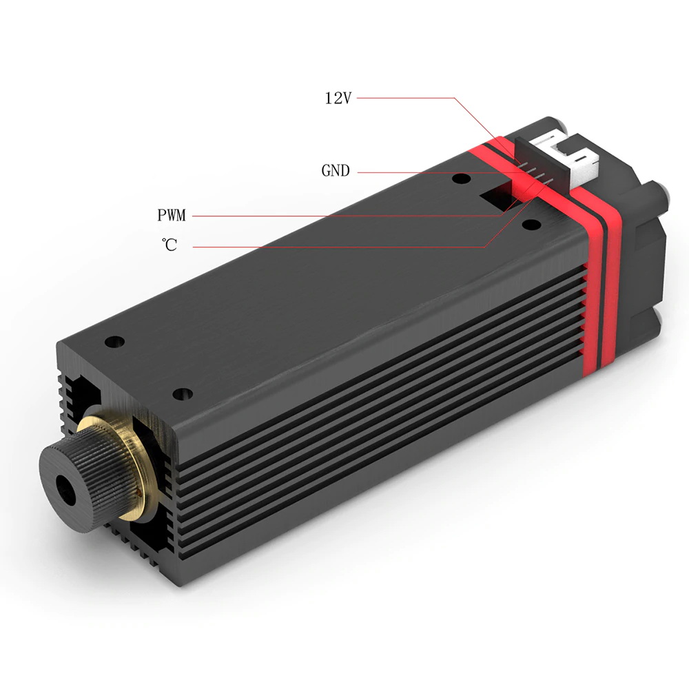
Do you have a datasheet or source for the reason to do that? It’s not connected to the GND pin on the laser. I was planning on:
12V to +12V on a 12V 5A PSU.
GND to Ground on 12V PSU and to ground on Carbide controller.
PWM to Pwm pin on Carbide controller.
°C left not connected unless I later decide to read temp.
2 Likes
Yes, I also don’t understand why you would want to short out the temp signal to ground.
@neilferreri have you seen the NEJE laser wiki http://wiki.nejetool.com/doku.php
it mentions “NEJE 12V LaserModule Tester V1.0 will be released” I believe its this;
https://www.aliexpress.com/item/4001097232962.html
3 Likes
I would imagine you’d want it to be grounded so there is no reading at all.
There’s a voltage there that can be translated to a temp based on the thermistor in the laser module. The laser isn’t reading a value. By connecting that voltage to ground, I’d think you’d mess up your reference voltage.
Anyway, I must’ve crimped too tight and my °C wire broke off as I was plugging in my wire. For now, my decision on what to do with that connection was made for me.
Everything “works”, but I’ll need to do tests on feed and power. I tend to rush to see if things work and then later, if I need to, make them tidy.
NEJE 7W from Amazon… Just the laser. I got the last prime shipping one.
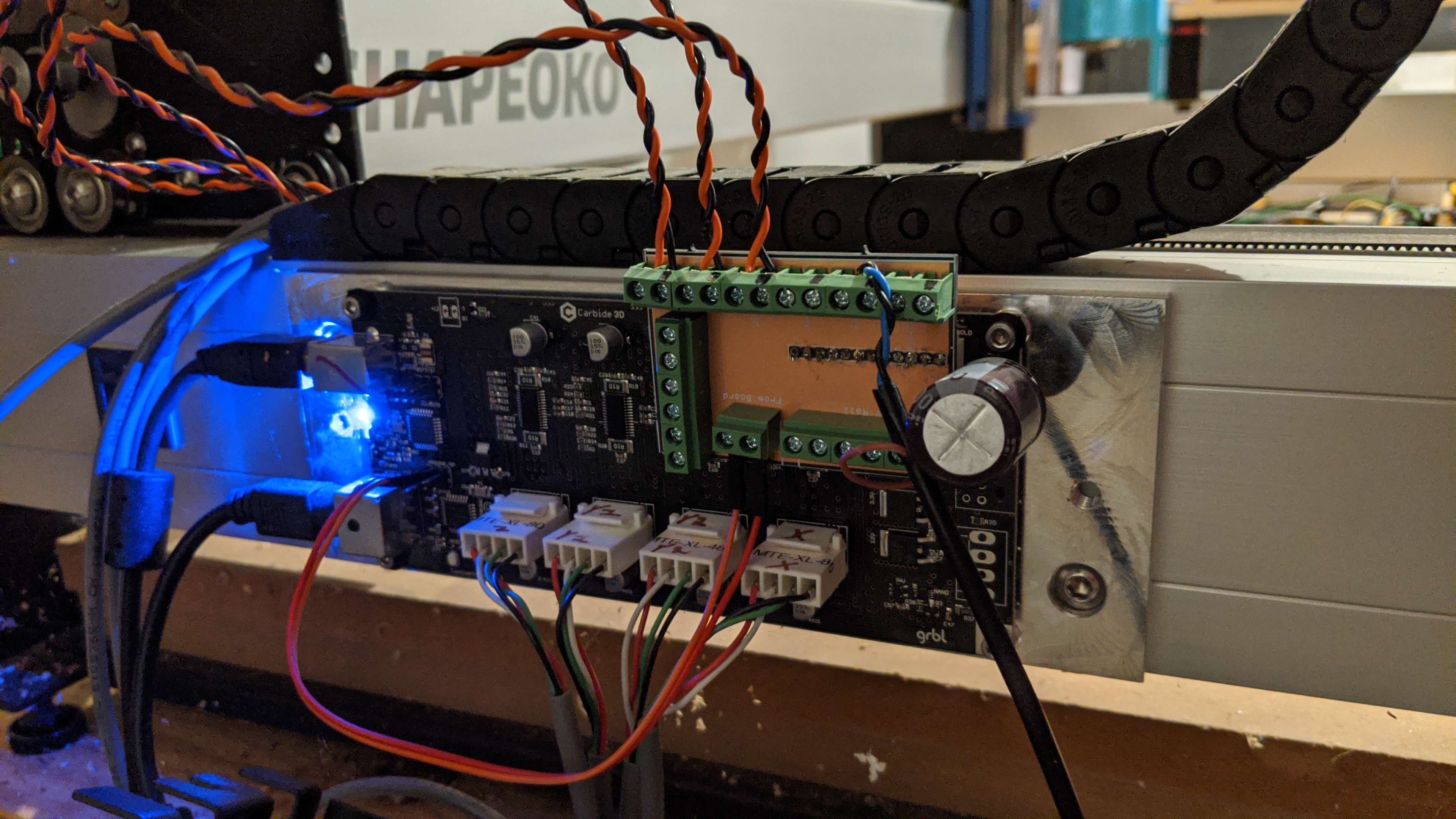
I also made a PCB to help with my connections.
Still not sure what I’m doing when focusing, and I couldn’t fit my fingers under the laser to turn the lens. 3D printed a wheel.
Also I set my zero too far back on the Y, so I couldn’t finish my test (that’s what I get for doing this stuff at 1:30am).

6 Likes
Hi @neilferreri, stella job! I’m interested in your little pcb and please forgive my ignorance. Can you give some more detail about it and its rationale.
- Is it removable or soldered to the CM board.
- What are the unused connections for?
- I can see its connected to the ISP but I can’t see where the laser is connected. I can see a connection to the probe (assuming they are still in sequence) but what is the brown wire from that lead?
Aside from the horrible soldering job (my cheap iron didn’t like the ground plane), it’s basically a board to just make connections easier.
I had a 12pin connector for the limit switches and probe, and I had to keep pulling pins, finding connectors and crimping. I wanted it to be easier to add and remove things. I had to use different screw terminals than I planned because I didn’t measure the pins (Remember, I tend to rush as I have 3 young kids and do most things after everyone is in bed), so the silkscreen is covered.
Anyway…the top row of screw terminals is just the SO3 pins broken out for easy connections.
The 6p terminal on the left is 3 connections for PWM/GND.
The 6p connection bottom right is a 5V rail (for active probes, inductive switches, whatever).
The 2p connector on the bottom center is a PWM and 5V input which I pulled from the ISP header.
It all plugs into the board with a 12p connector on the bottom of the board. This is an older board without the “Nomad” connector.
3 Likes
Thanks very much that’s very clear. It also makes great sense to do for easy testing and development.
That’s really why I did it.
Anyone with a J-tech or OptLaser chime in on what I’m missing with the cheap NEJE? What’s the benefit of those? Here’s the one I got.
https://www.amazon.com/dp/B088FJJ66M/ref=cm_sw_r_cp_apa_i_AVcnFbGKCCW2F