How do folks order their toolpaths? Seems to me there are at least a couple strategies one could take:
most violent last: example vee, big pocketing, contour (leaves most stock till end)
fail fast, contour, big pocketing, vee (does op that is most likely to fail first)
I am failing a lot lately, mostly due to my ramp up on Fusion. So I am thinking about trying the path that fails the fastest and I guess if that leaves enough structure that there is the physical support needed for the detail work then all is well.
I tend to do the cutout contour as very last, to keep structure in place…
but beyond that (assuming geometry gives full freedom) I tend to go from the biggest endmill to smallest (with V being sort of the honorary smallest by declaration)… and within an endmill size, pockets before contours
I cut t he least invasive first and the cutout last. I suppose pockets that do not go through could be cut anytime because your structure of the piece is still intact.
You mentioned that you are failing a lot lately, specifically how are you failing. Is your workpiece moving or are your tool paths not machine correctly. There are a lot of people on the forum that are pretty good with F360 and posting your file might help get some feed back on your methods.
Very much appreciate it. I am definitely trying to do my due diligence of trial and error before coming here with questions.
I had hoped to make a parametric fusion file that I could just have to go in and changes some parameters, font, and text with a quick regen of toolspaths and violla. Toolpath regen mostly worked but needed some tweaking. My hopes of almost not touching the fusion file to get customized gcode were a bit ambitious…but I can get close…if I can get the toolpaths right to begin with.
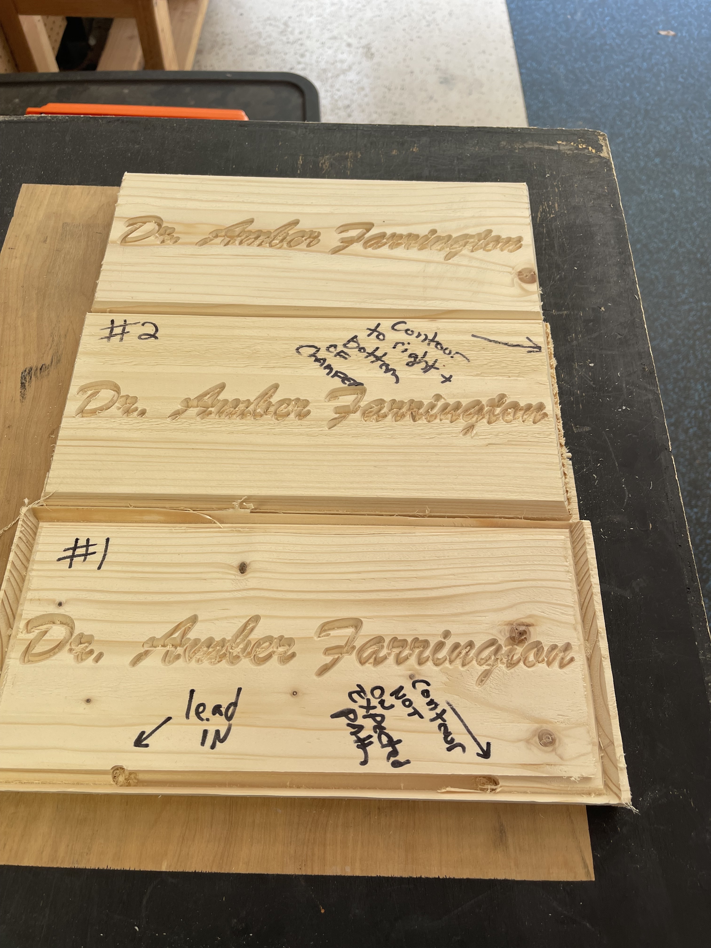
1: Issues were lead in was turned on for the rough contour path and I had the the arrow pointing the wrong way on the tool path selection so it cut, I believe, on the inside of the selected contour instead of on the outside.
2: Removed the lead in an put the bit on the correct side of the contour to correct issues from (1). New issue: Contour path is a bit low and to the right on this one. Could have been a machine zeroing issue (though I didn’t have a need to zero x/y after the start of this cut) or it could be a toolpathing issue. Also realized I didn’t leave enough stock on the periphery to actually hold things in place towards the end.
3: Said “Why am I fighting with F360 for something I can do easily in CC. Let me cut in CC to prove to myself I am not an idiot.”…and so I did. Corrections: made the cut model slightly smaller as to leave more stock to grab on the outside. Turned out relatively good compared to both attempts in Fusion.
Issues present in all models: depth of cut on the vee (.25) path was too much for size of this piece and the lettering involved.
I’ll add that if I am using a irregular piece of stock that makes it hard to zero or didn’t actually zero my machine zero initially and just eyeballed it, I’d want to contour first because otherwise it might be impossible to find the same zero again if the cutting operation if interrupted (power loss, computer crash, you have to abort, your depth is too shallow, etc.)
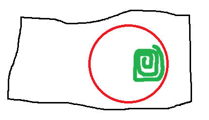
Imagine in the illustration below that your stock is like the black outline and your actual contour is the red outline. Your brilliant adaptive tool path starts hogging out the green, and then you lose power due to a storm. How can you possibly resume from there? If you had contoured one or two depths and then experienced the same power loss, it’ll at least you give a chance to rezero the machine with your workpiece to the best of your ability.
In that situation, I would mill a pocket which the BitZero would fit into which would match where the origin should be — if the file has to be cut in several sessions, just place the BitZero in the machined pocket (just a suitable “L” shape pocket will work — I did one for a v1 for two-sided work: A simple technique for two-sided work )
Yes, there is more than one way to skin a cat. I don’t have a BitZero, but I suppose I can also cut an indexable feature into the raw stock and try to index from that correctly. The important thing is to have the foresight to anticipate this if your stock is really valuable to you (jointed and faced / bookended / color matched / last piece that you don’t want to scrap).
Those numbers are based on the machine homing sequence. As far as I know Carbide3D hasn’t guaranteed 0.001" - 0.002" accuracy between separate homing sequences (what I can achieve repeatability-wise probing manually). Yeah, I understand if you are just making a tray for your tools even 0.01" doesn’t matter at all. But in some cases you want to start with the best you can do and you might end up with something that is good. If you start with something acceptable, you might end up with something that is rather poor.
But in case the homing numbers are really good, I’ll try to give that a test. Probe a fixed object 10 times between separate homing operations and see what numbers come out. I’ll post my results when available.
I wasn’t claiming 1-2 thousandth absolute machining accuracy in the above post (I was talking about probing the part location with the Shapeoko), but to be honest I’ve been shocked at the X-Y internal accuracy of the Shapeoko. For instance, if I contour a 7 x 4 rectangle and then probe it, I get a 7 x 4 within 1-2 thousandths. Now the Z axis I have the most trouble with (sometimes as much as 5-10 thousandths and end up either have tenons too tight or contouring through my double-sided tape or marking up my wasteboard. Most of the time I don’t caliper my final external dimensions, but the times I did I never had any negative shocks (certainly never 0.01"). I do use my height gauge more often and sometimes do find disappointments there.
I am surprised to hear that 0.01" thereabouts is the limit to your machine and process.
I have seen a few of the pics you have posted showing some of your upgrades. Very nice and shows somewhat of your commitment to get as accurate as possible…I like that.
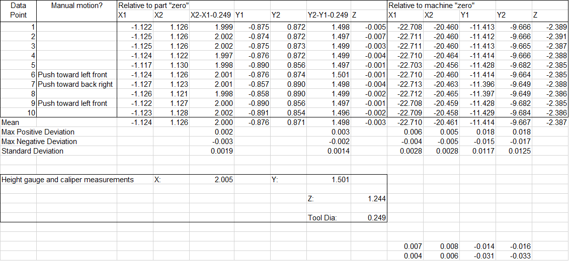
Okay, I performed my measurements on my Shapeoko 3 XL with Z-plus and inductive homing switches. I found a piece of scrap maple, bored a countersunk hole through it, and bolted it to my wasteboard. I then faced the top (3/4" straight router bit) and contoured the sides (1/4" standard Carbid3D endmill). I was targeting 2 inch length (X axis), 1.5 inch width (Y axis), and 1.25 inch height. What I physically got was a 2.005 X 1.501 X 1.244 inch block. The Shapeoko probed it as a 2.000 X 1.498 block contour.
Some thoughts:
Manual probing for the boundaries is generally very repeatable (1-2 thousandths as I had previously remembered). The absolute accuracy was good in this case for the Y, but 0.005 off for the X. If for instance X1 and X2 are used to find the part center, the average should still be pretty good.
The homing process can potentially produce very repeatable numbers (for instance data points 1-4, =< 0.003" absolute difference). But it is not always the case, and the error from homing to homing sequence can be significant (for instance between points 8-9, average 0.032" for Y). The homing sequence seems to be more repeatable if you don’t move the machine manually, but there can be still some discrepancies (for instance between points 4-5, where difference is ~0.008" for X and ~0.015" for Y).
Given the above, since my manual probing is not prone to wide variations, I will still probe manually instead of relying on the homing sequence to return me to the part reference location. The homing sequence can be very good, but is not always the case. With respect to the original discussion, I guess I’d have to concede that using the machine to return you to the previous zero is good enough for many cases. Certainly usable if you don’t have any other references to go from rather than give up hope completely.
I think I have more insight as to why my Z axis has more problems. It seems to be related to my probing where I sometimes overstep into the part and “lose steps”. On the X and Y, colliding into the part by 0.1" will lose steps, but will never lose steps when it is just 0.01". It seems the belt and mechanicals have enough give for it to be recoverable (elastic). But on the Z, it seems to be much less forgiving (i.e. will stall / “lose steps”) and it is not fully recoverable due to the Z-plus screw drive.
0.001" for metal work is a pretty high bar and you’ll have to put in the effort. When I previously looked at people’s accuracy postings for Tormachs for instance, I see that they have to be very careful and at times even walk up on the final dimensions to get 0.001" consistently. Generally not a clamp, run the code, and you are done sort of thing.
Vince Fab and others have pretty solidly demonstrated that low depth, wide fast feed cuts are the way to remove material fast, the rigidy of a hobby machine doesn’t lend itself to large depth engagement in cuts.
I regularly see < 0.1mm error in Aluminium, first cut without fiddling, and use a final stepover of about 0.1mm with a repeat finishing pass to get quite shiny things off the machine.
When I need to get something accurate setting up a parameterised offset in Fusion and running the first pass deliberaly oversize then sneaking up on it (in multiples of 0.025mm) by taking the calipers to the piece after the cut seems to work pretty well.
Hiding from the almost biblical rain at the moment thanks
In one or two dimensions at a time I can get down to the measurement precision of my calipers, see the examples at this timestamp machined on my pre-rails upgrade SO3 XXL
Where there are more complex shapes you are much more limited by the backlash of the machine and it’s very hard to compensate down to this sort of accuracy. I would not expect to cut a circle to this accuracy, or a set of tenons with tenon & gap widths, but well under 0.1mm, if I don’t get that I check for the loose belt or bolt.
Edit - It’s probably worth adding that until I got my Shapeoko precision was my Prusa i3 and my experience of machining was a pillar drill, a router and watching Mr Saunders, This old Tony and Abom79 on YouTube…