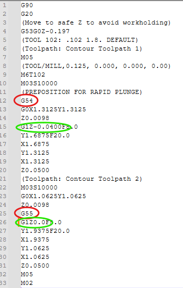
The only thing added is the G54 & G55
The first Z is relative to Top of stock, the second Z to the bottom, or slightly below.
The constraint you mention is controlled when you set the fixture offset on the machine.
CM will most likely draw both paths relative to a single Z zero. It has no idea where the G55 is relative to the G54.
More advanced controllers do ‘know’ where the offsets are. You set them using the controller.
With CM, you set the offsets using macros or MDI, and only GRBL is aware of their position.
As long as the offsets on the machine match the offsets programmed, you’re good.
The relationship is preserved in the operators head.
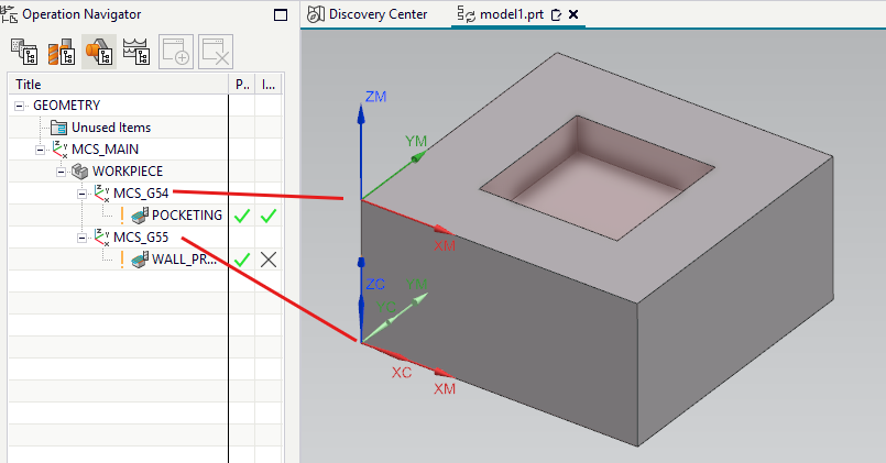
In NX, I can create multiple MCS (Machine Coordinate Systems) and assign a fixture offset to each. But all this does for the Gcode is add the G54, G55 as I edited them in above.
But I’m also working with solid 3D geometry.
What you’re asking for is multiple work offsets. Which is something that isn’t supported by carbide motion and I’d bet the controller doesn’t support it if ran by another program but I’ve never tried.
What others have said is correct that if you have an accurate material thickness then it’s not an issue.
Other controllers such as a masso are cable of multiple work offsets. But upgrading a shapeoko to a masso touch is far from cost effective. You’re better off buying a different machine.
I’ve never understand the craze to save a spoil board. My through cut profiles are programmed to go .010” into the spoil board for less post processing of the parts. It takes me 15 minutes to resurface my spoil board and about an hour to replace it because it’s on a vac plenum.
I’d love to have multiple work offsets and an atc. Only because I have v carvings I’d like to be able to have 4 on the machine at a time and each one have its own z offset. I’ve priced out the masso route. It would be. More cost effective to buy more shapeoko machines or a different machine.
Yep. Yep. Perfect material thickness and wood do not coexist.
Which is EXACTLY WHY the feature that I have imagined would be so wonderful.
Sorry to everyone that seems to be upset by me asking about a possible feature that would help most of us perform our work faster and better. My bad. Didn’t know this was some kind of forum foul. Won’t happen again. Trust me.
No one’s upset. Just trying to understand & explain.
If anything, realistic. Looking at all the enhancement requests on @robgrz 's plate, It may be quite some time before we see multiple work offsets. So the best we can do at this point is offer workarounds.
I never asked for a workaround or a job as a coder.
To those trying to “help” me, thanks.
I am one of those weird people that actually say what they mean. I wasn’t fishing for help. If I needed help, and I have PLENTY of times, I would have asked for it. AGAIN, I was simply and only suggesting a possible future feature based upon real world work flow.
If you wanted to make a feature request and don’t want people to offer a solution then I would suggest you post in the feature requests sub forum.
And perfect thickness wood does exist. That’s why they make jointers and planers and you can use your cnc router to face material to make it flat. None of this will save you from your issue that requires you to accurately measure and enter the material thickness of every stock piece you use.
Even with a metal piece, if I want it dead flat I will face at .005" at a time. I touch down on the material and face it. If that doesn’t clean up the whole surface, I go into the zero setting screen and call the current 0, Z.005" and run my facing pass again, rinse and repeat…
I was a metal fabricator for a while so I get that. I hated, hated wood when I first got into it, moving from metal. It has been a long battle, but I have made my peace with wood and actually kind of enjoy it now. But NOTHING beats welding metal parts together!! I miss that most of all.
See, here we go. In my original post I specifically asked if I was posting this in the wrong place. So thanks.
I have been a carpenter and finish carpenter for more than a decade. I have a planer and a jointer. It is a fluid medium that moves due to physical stress (in and on the wood) and even the amount of humidity in the air among other things. Do you have any idea what happens when you attempt to plane plywood? I tried it and it’s not good I can tell you.
My calipers tell me that high quality plywood is far more consistent across the surface than planed wood. Before the comments go wild, yes I know it depends on the species of wood and the planer and the atmosphere and the mole density of hydrogen molecules etc.
The machine has no way of knowing where you put your part, how thick it is, or where you set the fixture offset(s), unless you tell it. The operator needs to know how & where to set up the job, which tools to use, and should know the machining strategy for each path so they can watch and know it’s doing what it should. Any time a human interacts with the process there can be errors.
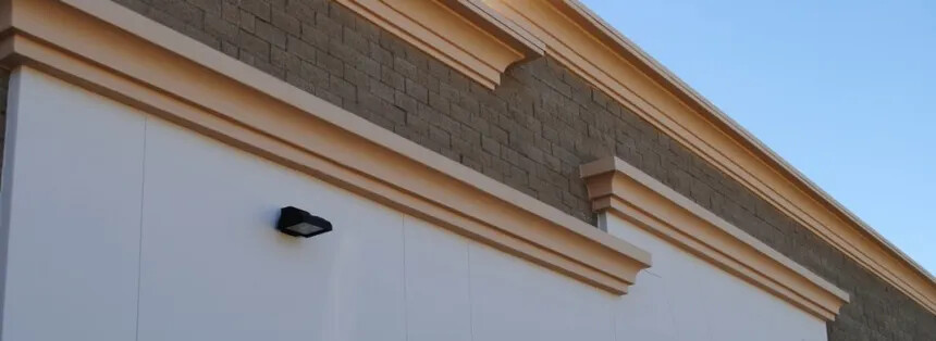
Our tract house in California had a metal frame, sheet Styrofoam insulation on that, and those type of “architectural details” that were hot-wire cut from Styrofoam and attached to the surface, and then the whole outside was sprayed with polymer-modified stucco. Flexible but earthquake-resistant…
This was not moved to the Feature Request area because it was phrased as a question.
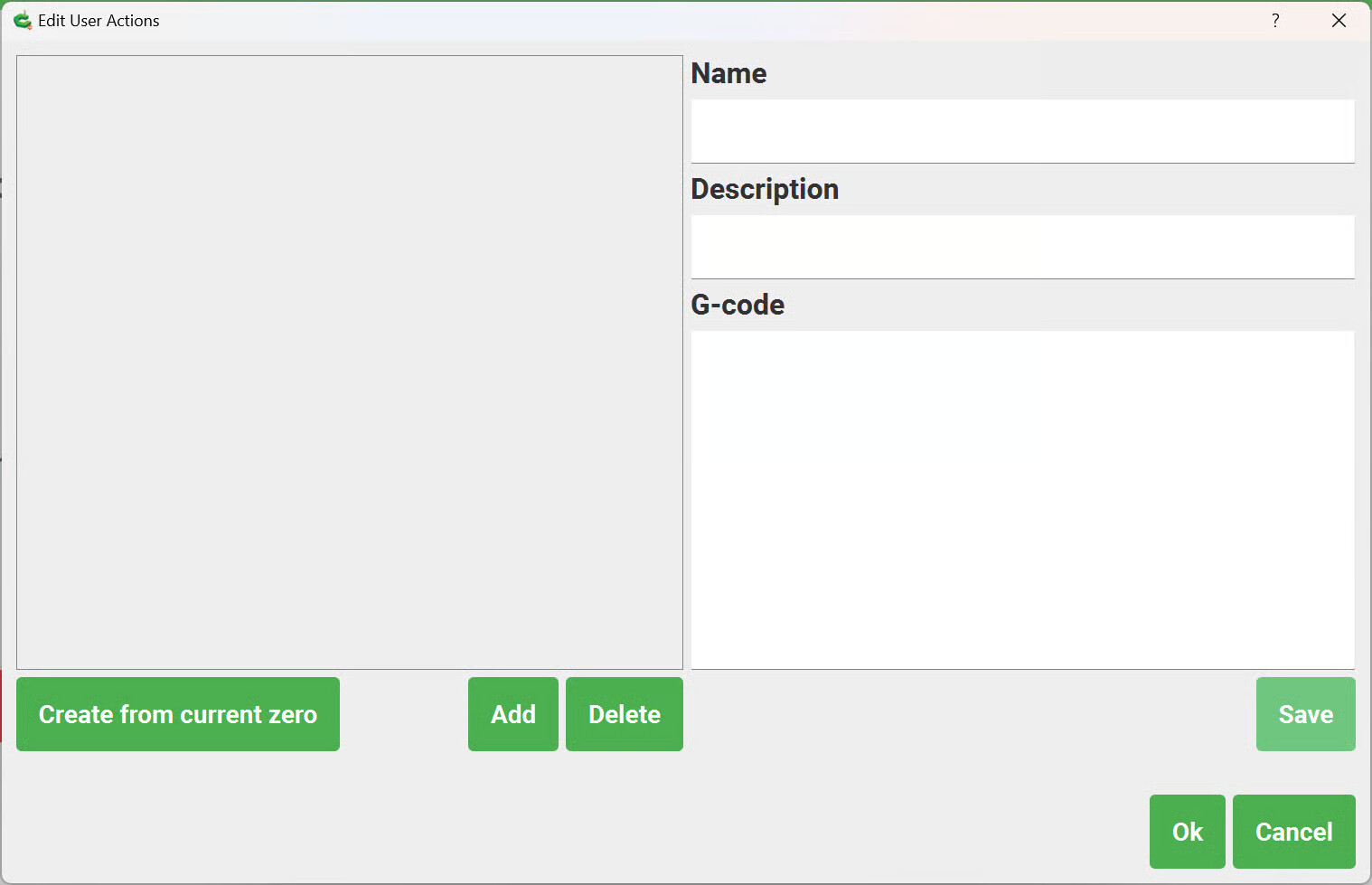
To expand on, and make explicit the answer, Carbide Create/Motion do not have a direct facility for this and it would be necessary to use separate files, but Grbl does support G54–59 Work coordinate systems, so it could be done using some other software — depending on what one wanted to do, it might even be possible to set up a Quick Action to facilitate this, but the usual approach there is to set a zero based on current machine position which may then be referred to — there’s a button for that, “Create from current zero”:
Folks may use whatever software which they wish with our machines, and we have a couple of areas for discussion of same, but if things get too far afield, a different venue might be better suited for such discussion — we ask that folks keep in mind that this forum represents Carbide 3D and its machines and software and to keep the forum rules in mind.
My approach for the situation initially put forth:
is to use a micrometer to measure the stock thickness, enter that into Carbide Create, and set the zero at that height relative to a just-flattened spoilboard.
Yeah, Will, that is exactly what I do for set up and it usually works pretty well. ALL apologies for breaking whatever rules I broke. I was specifically speaking of CC, CM and the shapeoko as I thought that this was the forum for that. I ONLY use CC and CM. In my original post I asked If I was posting in the wrong place, so again, my bad. I seemed to have stepped on a preverbal land mind in here. Lesson learned. Thank you for your attention.