Figured I’d do a quick write up on how I did a tray thing, and also post the file because it’s a fairly simple design, but can be modified to add different logo/initials/names/etc.
I’ll also add the files to cut rocket eventually. But figure the how to might be more better.
I had some butternut that restricted the height, and also was working on the nomad, but I tried to set this up for the shapeoko as well. Also worked in imperial units, which I’m not the biggest fan of.
I started by making the bottom of the tray first.
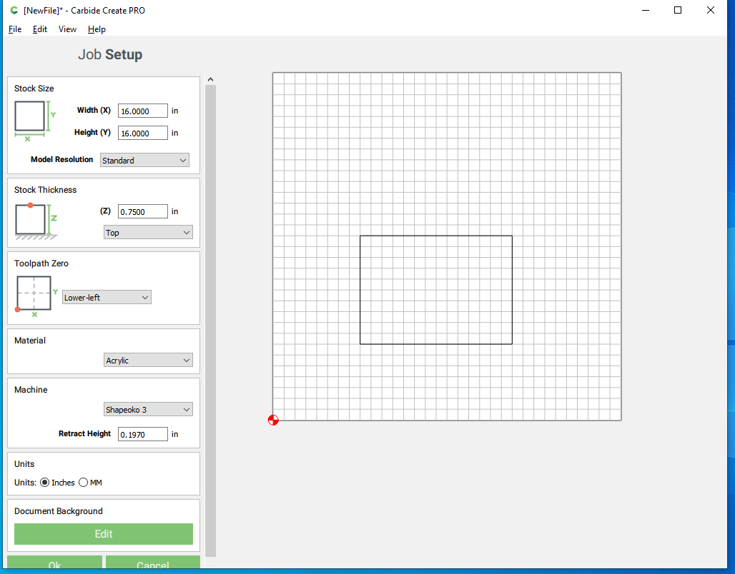
Anyways, setup stock and stock thickness.

Laid out the squares
Now we move over to the carbide create pro features.
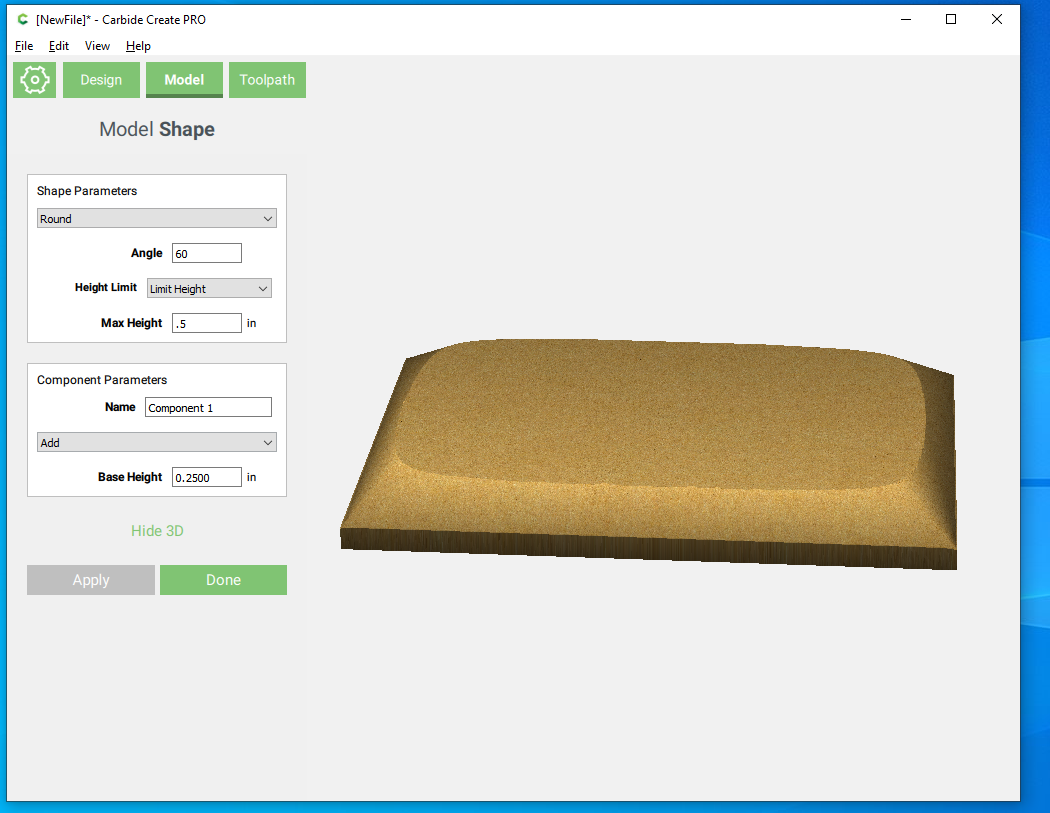
So this could be accomplished either all at once, or into 2 different operations. The way pictured is selecting the outside rectangle, selecting round for the shape parameter, making the max height .5 (with a height limit) and then start the round portion .25 above the bottom.
Second method would be to select the outside rectangle make the first component a .25 inch solid add, without a round. Then adding a second component, select the round function set the max height to .5 (and again limit height, and then select add at the component parameters and leave the base height at zero.
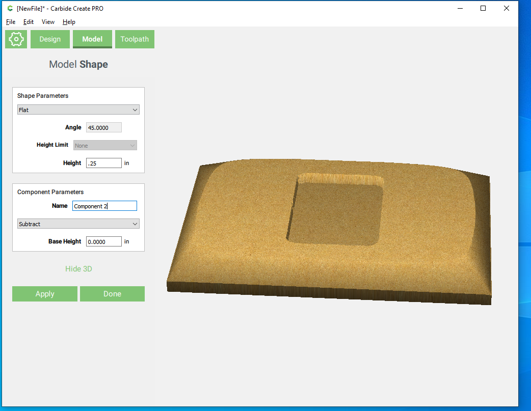
This part was totally not needed to 3d model. I’m effectively making a pocket to put some contrast wood in. I used the subtract parameter to remove that segment. But could just do a contour with the square selected.
Pretty simple tray bottom, but I think it looks pretty good and was quick to whip up in Carbide Create Pro.
I cut out a slightly undersized piece of paduak that was about .25 inches thick.
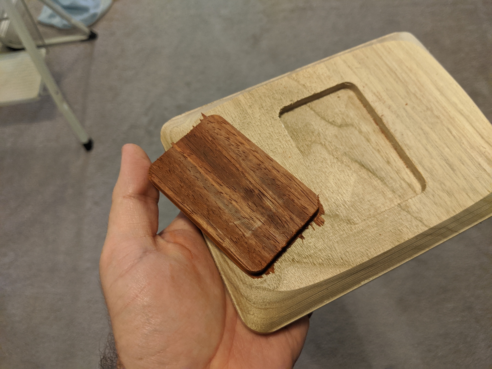
Then glued that in.
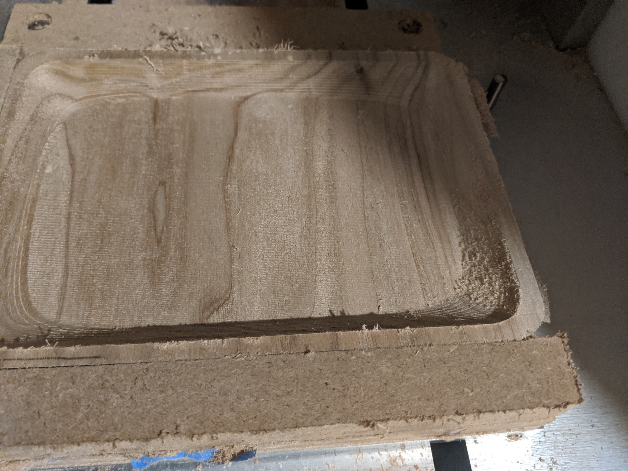
I made a quick corner to throw the tray against for milling the top.
So because the floor was a max of .25 inches thick (the start of the recess) for the top I’m going to make the floor start at .30 inches thick, but I do drop that a bit later.
Here I’m going to start with a solid object then remove the tray portion.
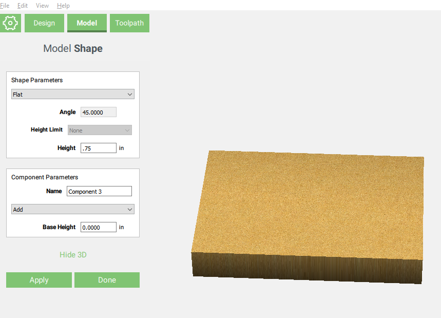
So I add the full .75 inches.
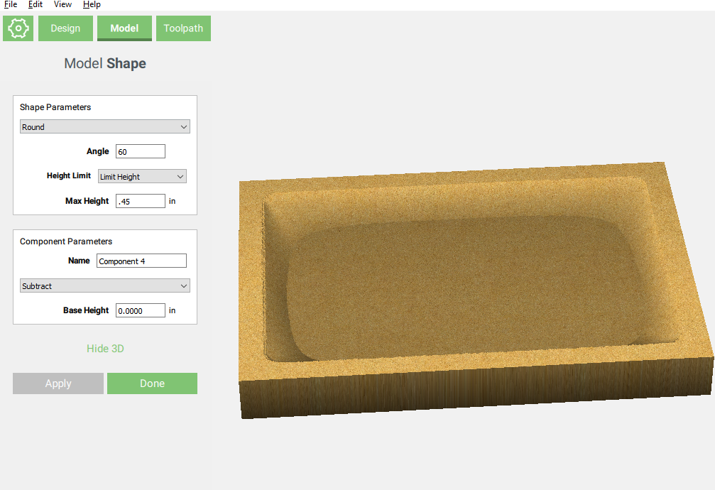
Then I use the subtract operation with the round shape parameter. Max Height applies to the max amount removed in this case. So getting to .3 inches on the floor I need to remove .45 from the top.
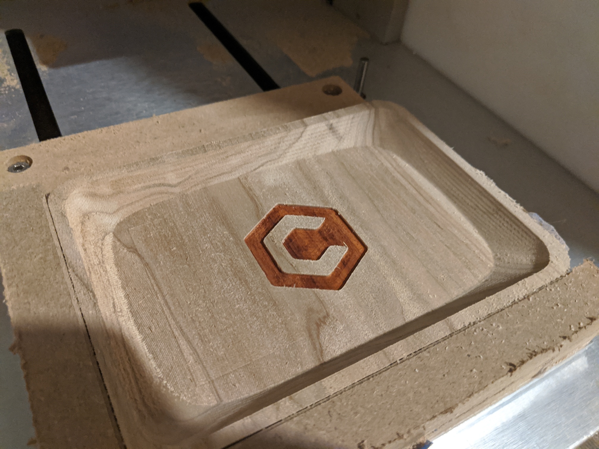
Then, lets say that we wanted to have a logo stand out in stark contrast. Or perhaps someones initials.
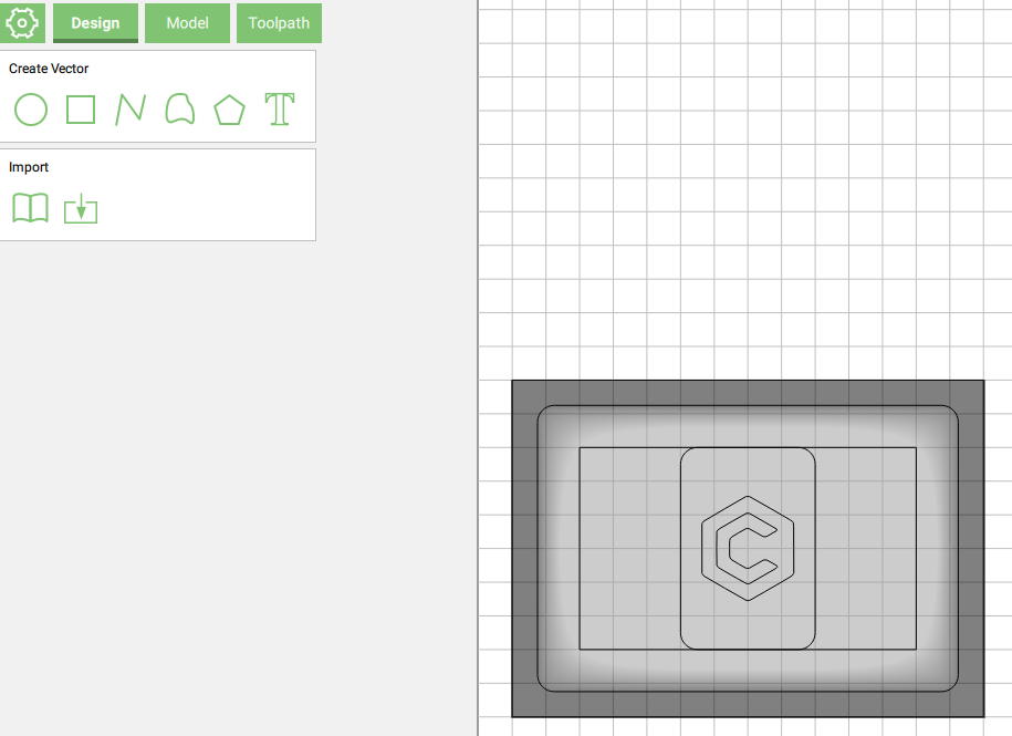
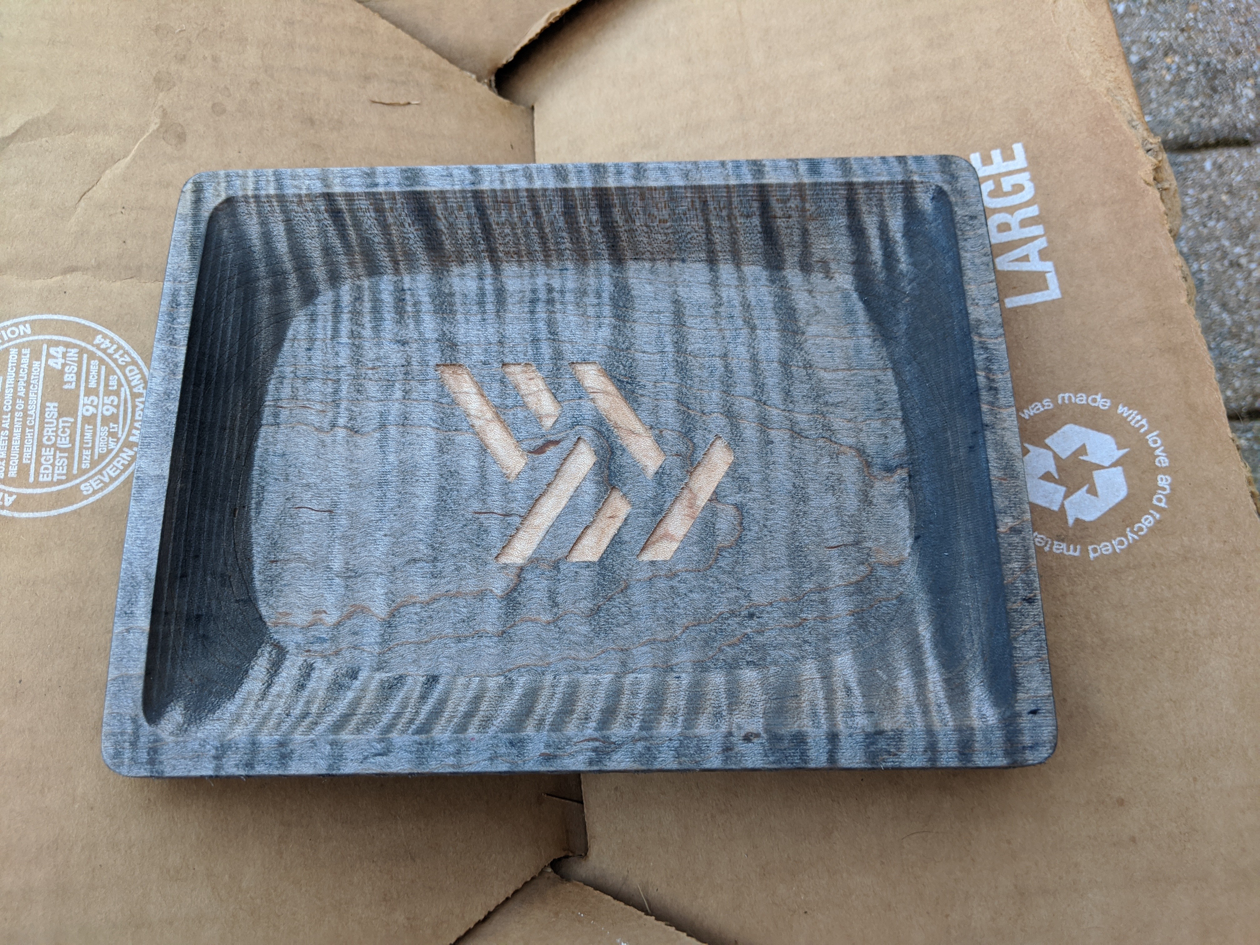
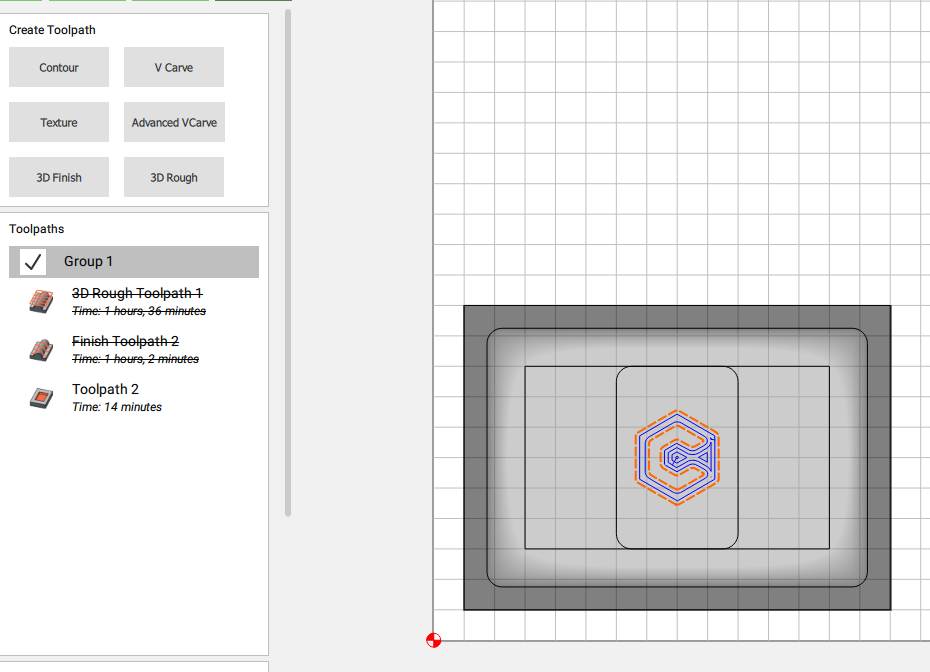
I pulled in the carbide 3d logo as an svg and put it center in the smaller square.
I could’ve used pro features to drop that feature down in the 3d model, but wanted to sort of sneak up on the feature, ultimately landing on .525 pocket
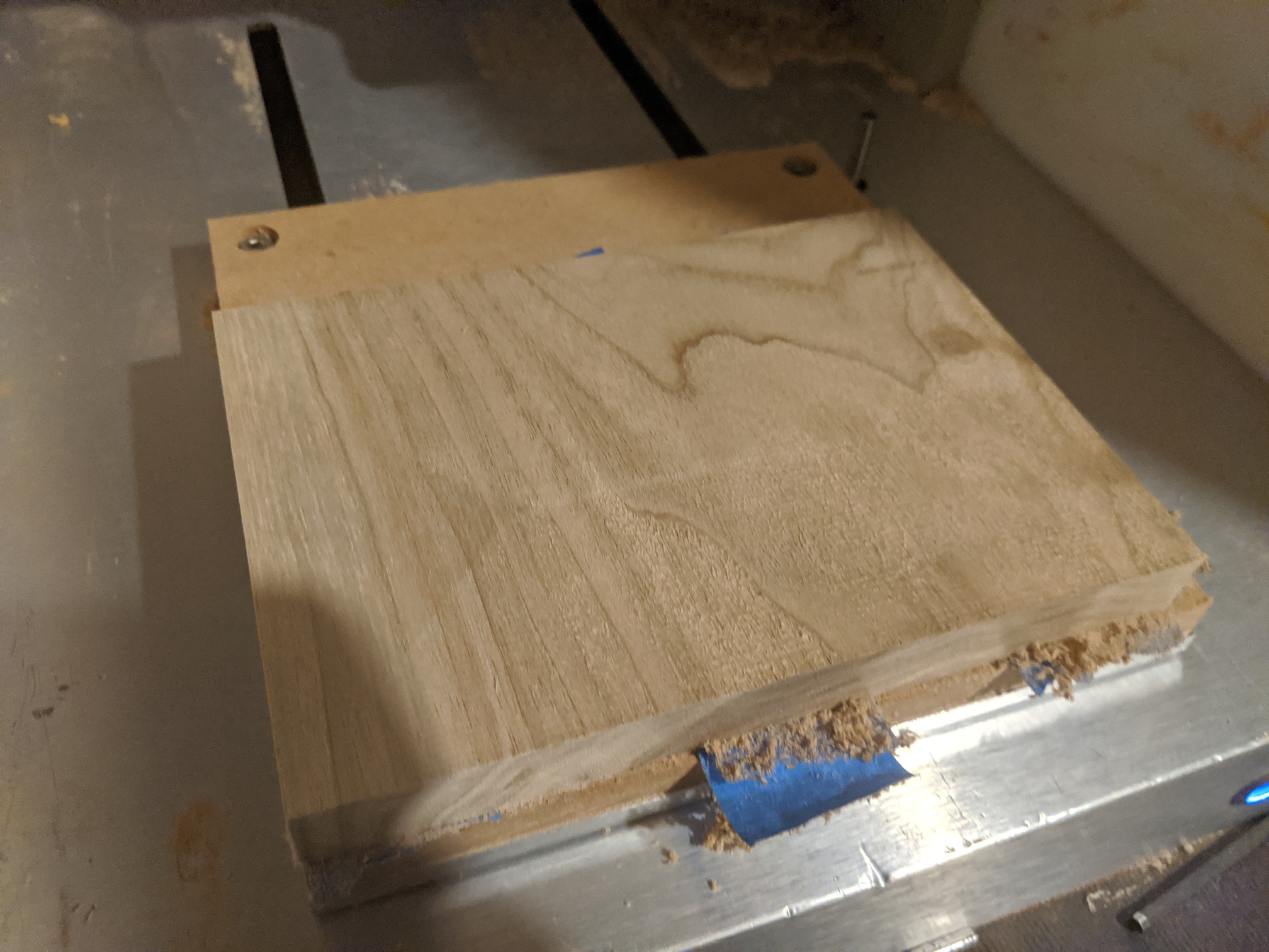
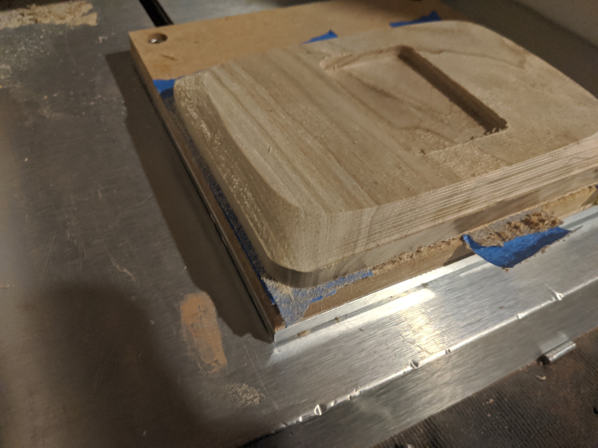
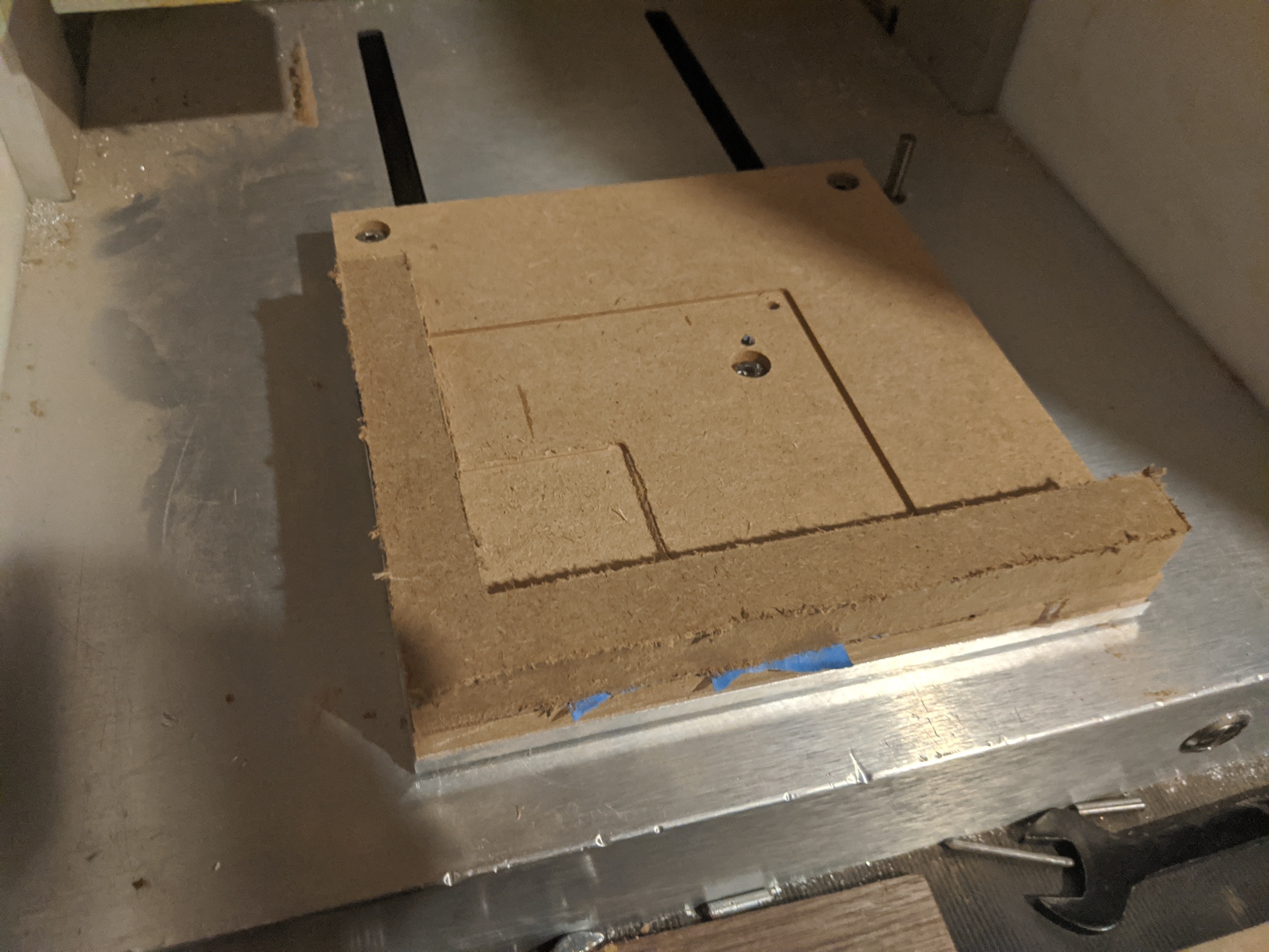
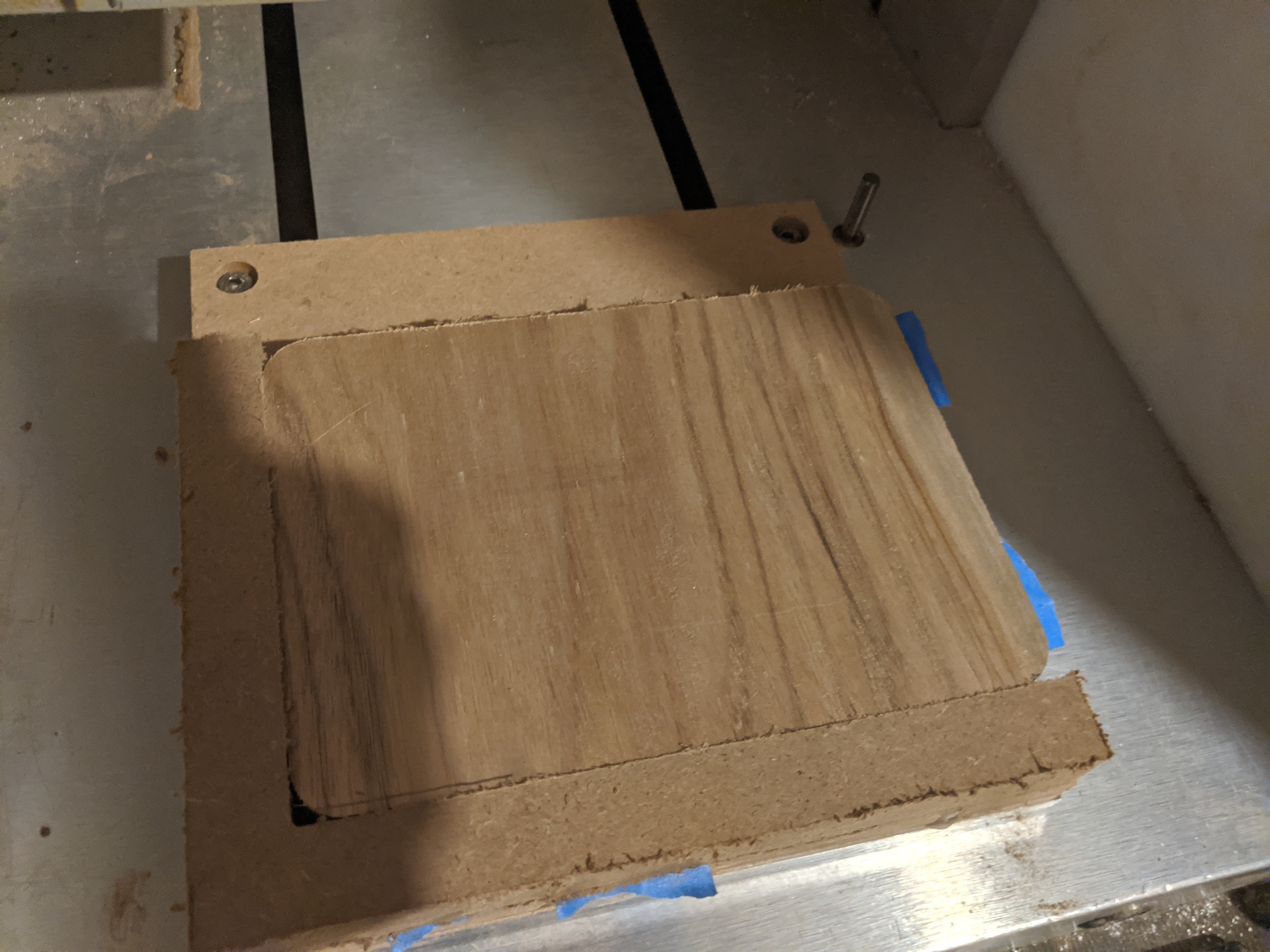
More machine pictures:
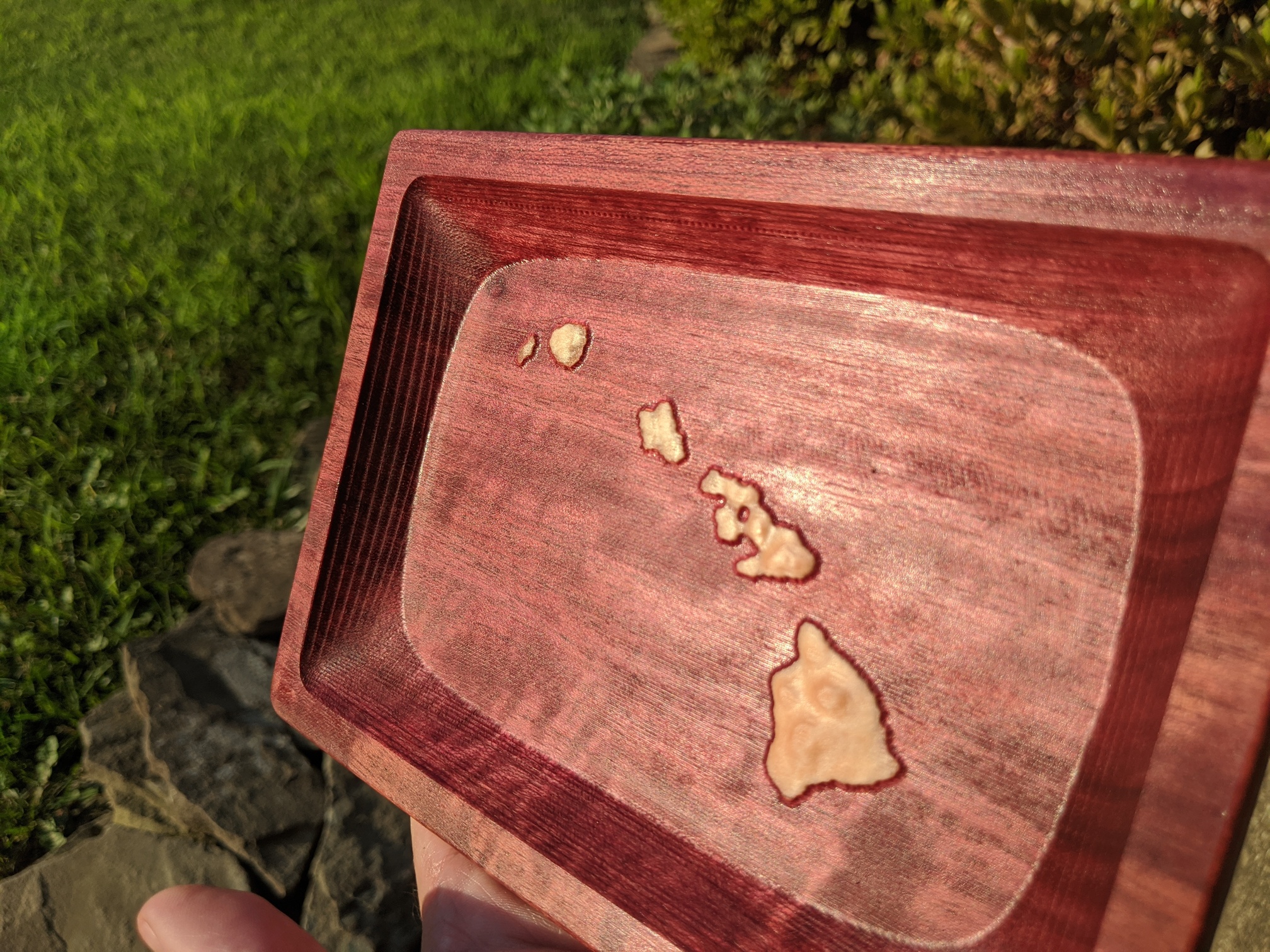
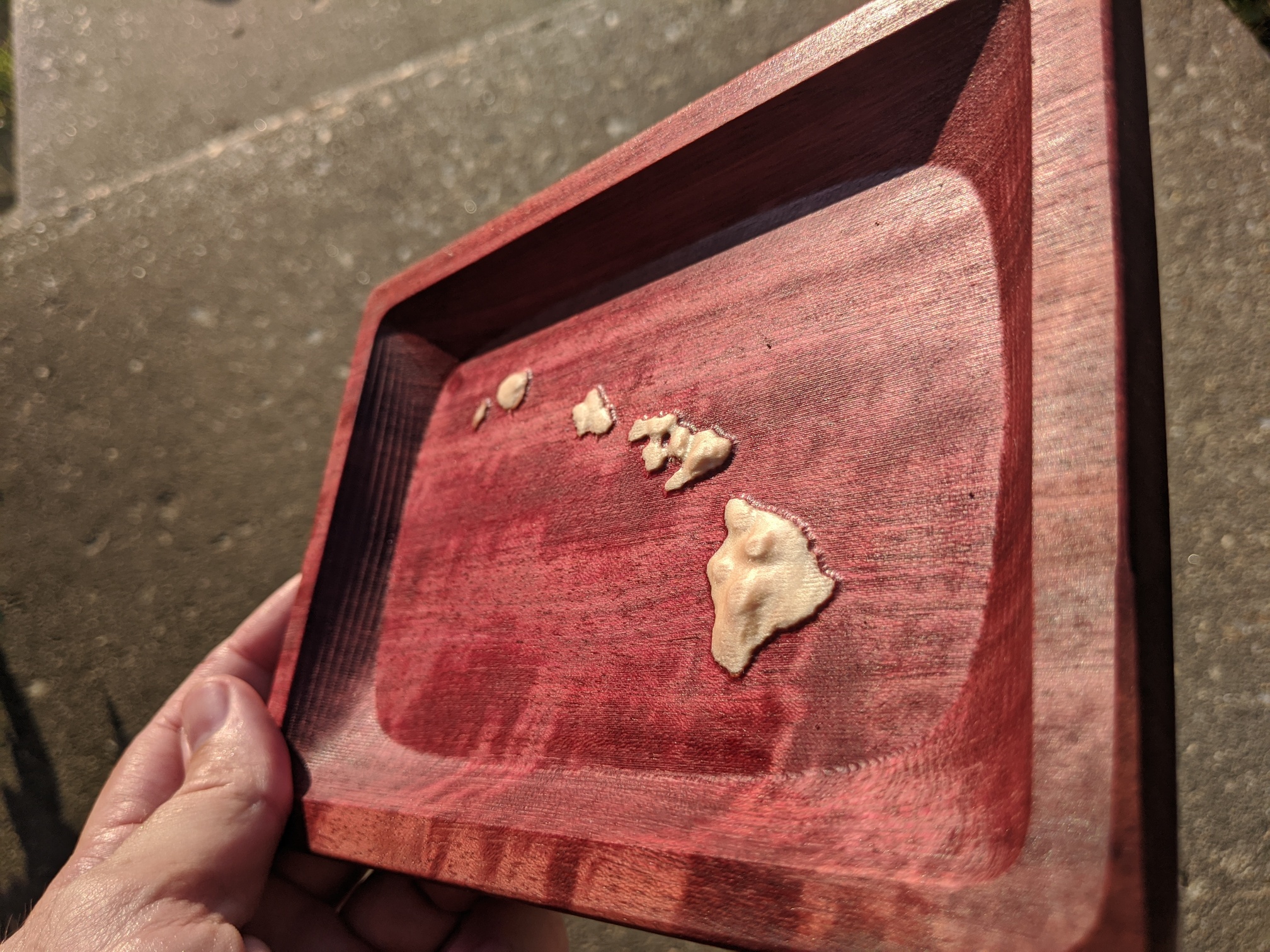
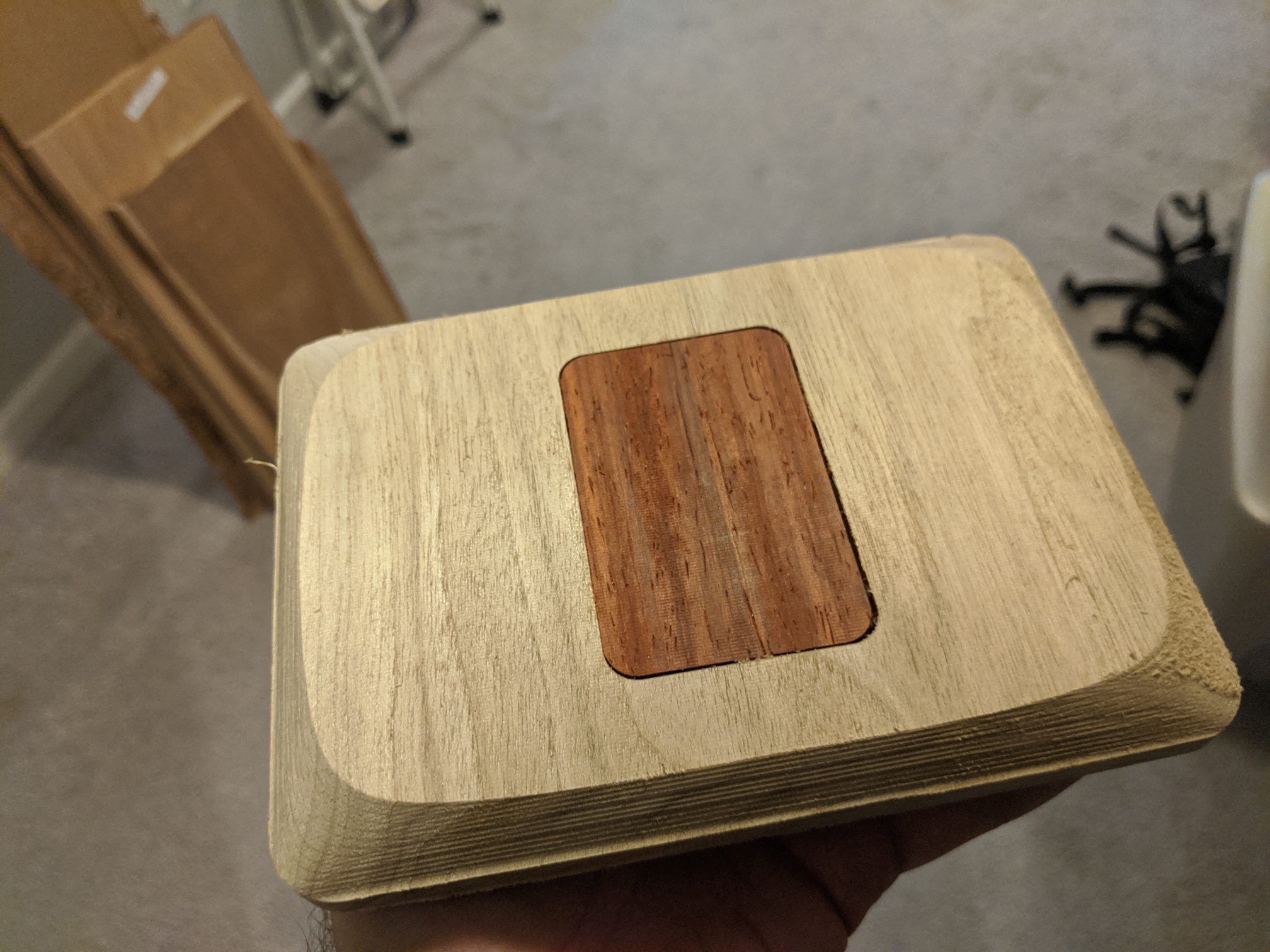
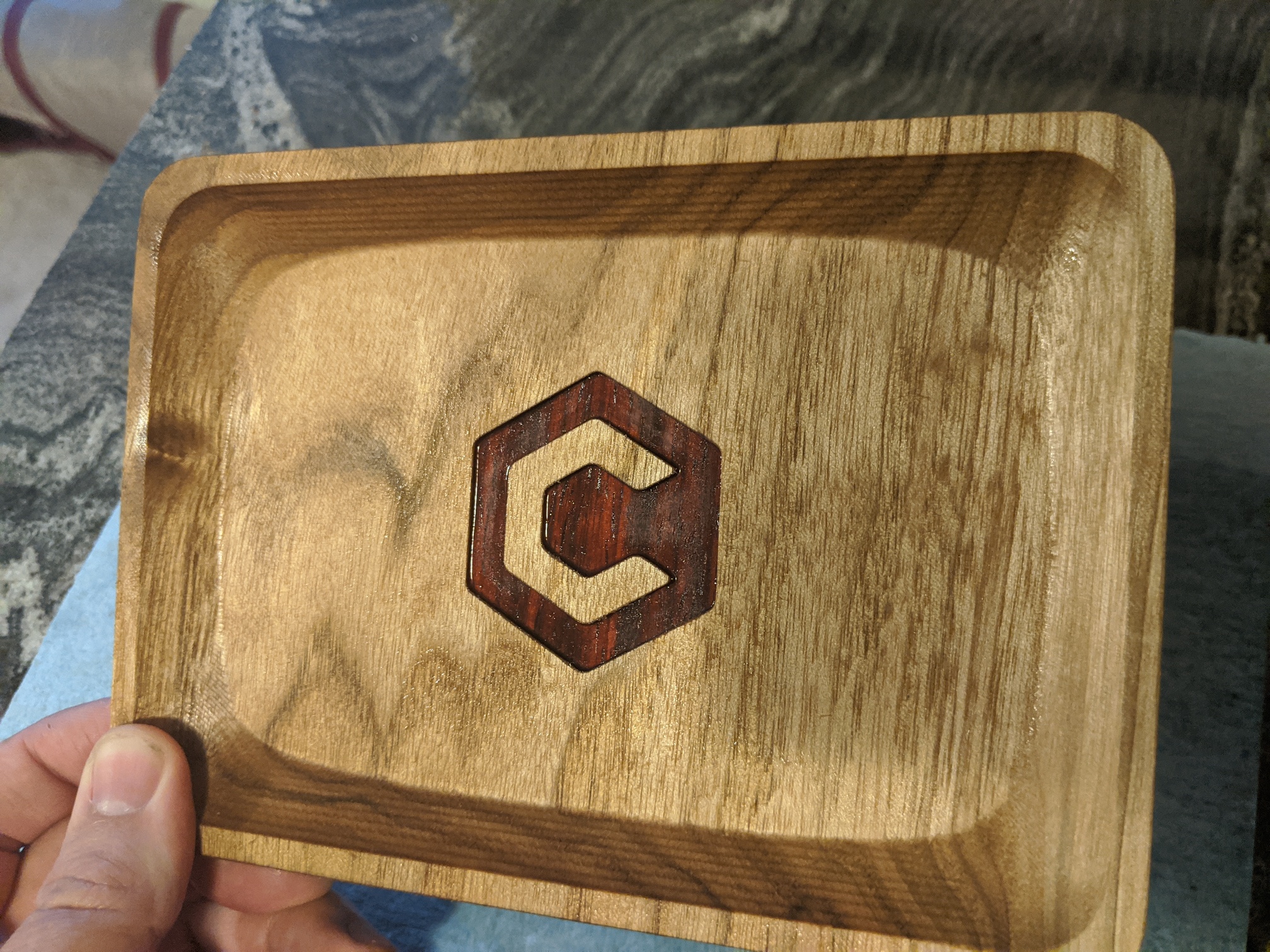
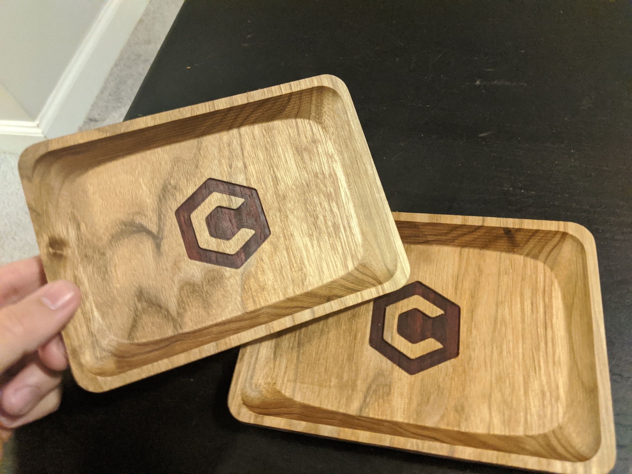
And here’s finished project:
And here’s files:
tray front.c2d (115.1 KB)
tray back.c2d (106.9 KB)
Should be easy to replicate, but also you can pull the files and replace the logo. I was going to do a raised version (similar to what I did with the New Zealand tray a few contests ago), but not sure how functional that would be.
Feeds and speeds need to be changed as the current file is for the nomad speeds/feeds.