I did a facing operation in Fusion 360, using carbide3d’s 1/4" end mill. It removed material in both directions. The feed rate was 1000mm/min with a 5mm step over and I took out -2mm on the Z.
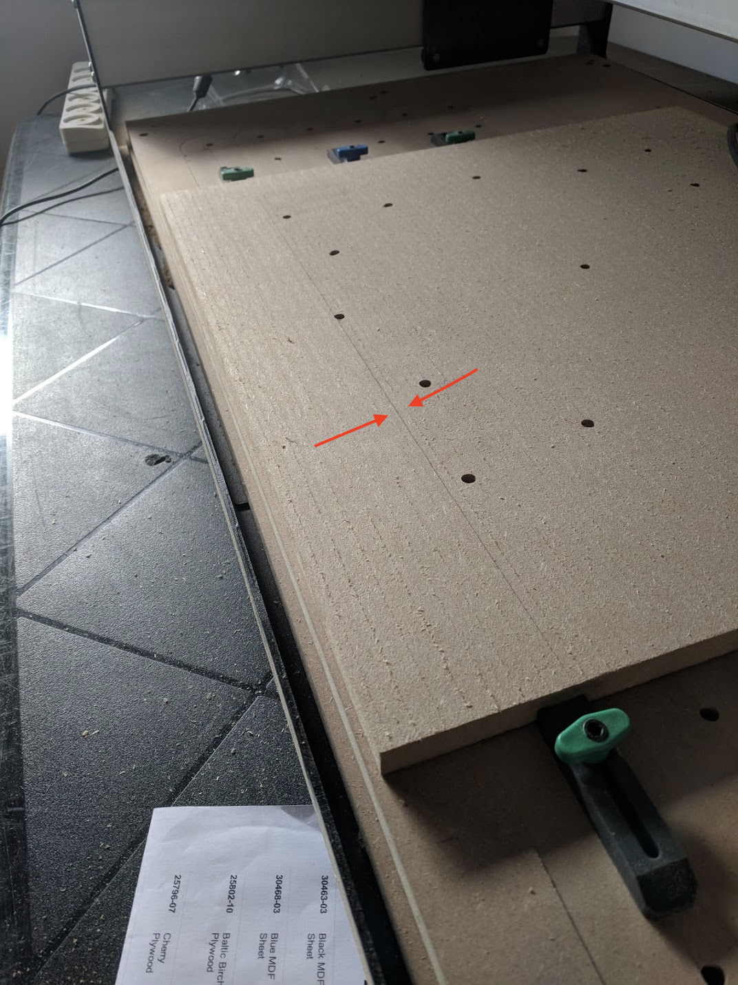
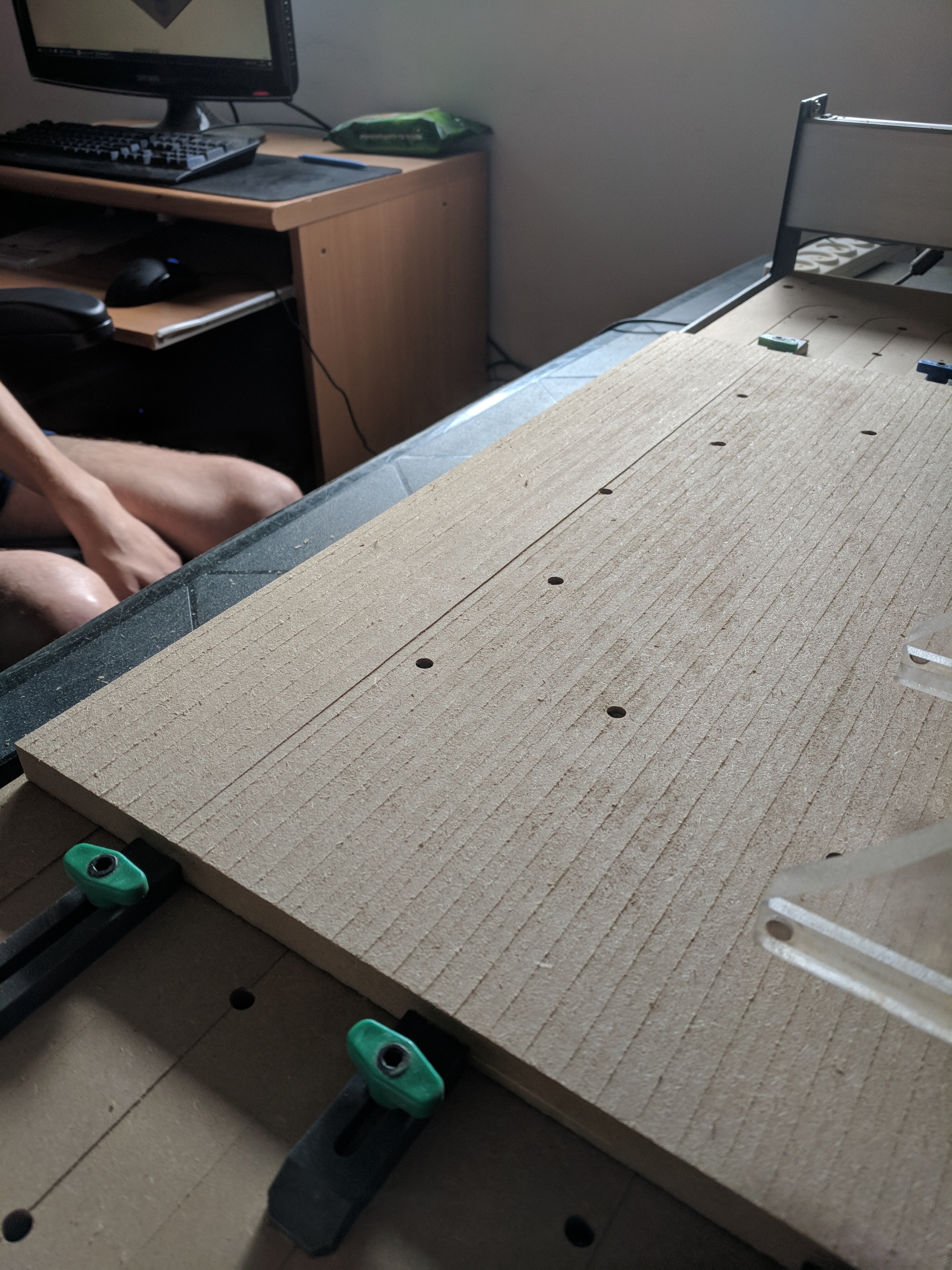
First, the tool left some visible lines along its travel path. It’s not uniform across the entire piece. If I feel it with my finger, the right side is more noticeable. Not sure if it’s normal, but nothing a light sanding can’t fix.
Second, and this is the weird part, there is a much more noticeable dip at the line I marked red. I want to say around 0.5mm at the far right and slowly getting back to normal. I was watching the machine the whole time and nothing weird seemed to happen around that time. My first thought was squareness, but why only there? Anything I need to look out for?
My first thought is the zaxis isn’t square to the board. If you try to gently rock the carriage forward and back does it have a lot of play? I found I needed to just slightly tweak my eccentric nuts on the z axis assembly to prevent that from happening.
There’s some posts and a video Winston Moy did about checking squareness of the spindle to the worksurface.
Clarification: direction of travel would be into/out of the screen, not horizontal. Essentially one side of the bit cutting slightly deeper than the other.
I really wish there was an official guide to squaring the machine with lots of pictures and videos.
I feel like the wiki and various videos out there don’t do a good job of explaining it to someone who doesn’t have prior knowledge in machining (big chunk of Carbide3D’s target audience). I actually haven’t got a clear idea of what to do next (aside from Daniel’s tip).
I’ve seen that video a number of times (and others too) but I guess my level of understanding is below being capable of following his steps in a short 9 minute video. Hence why I feel an official guide that goes into more detail has a place.
You’re instincts that it’s weird for it to be deeper in one spot is right, you can check the y rails to make sure there’s no debris though not sure that’s it. Belt tension is the issue on so many issues and yet it’s the hardest to communicate also.
The problem w/ a guide is that every machine can be off in a slightly different way — we do have some notes from tech support, but it’s better if folks have specific issues with their machine that they contact support@carbide3d.com and describe their problem and we can sort it out personally.
The big thing is (excepting the wasteboard) work from large to small. It can be a maddening tailchasing thing, but if you’re patient, and go through things methodically, changes / adjustments will become smaller each time and the machine will be squarer w/ each pass.
Here are the notes:
Please note that on an XXL, (or the long axis of an XL), being 1/16" is about 1/10 of a degree. Things which folks have had to do:
clear the powder coat out of the holes
drill out / enlarge the holes to allow for adjustment of the plates
Its deeper in spots because you are “surfacing” the board for the first time, it’s liable to be deeper in spots.
If it wasn’t on your first pass there would be no need to surface it. Get a bigger surfacing bit, shims or aluminum foil to shim the bottom of the spindle/router holder{ looks to be sagging a bit} Double check your wheels are snug to the rails.
There is a learning curve and honestly should be learned the hard way so you know your machine. It can be a dangerous machine and needs to be respected and not just read about with lots of “pictures”. That being said there is lots of help available , roll up your sleeves and ask away. G/L Ray
Before shimming I’d still make sure the nuts holding the Z axis plate to the rail are tight-but-not-too-tight. It should move smoothly but not allow much rotation front to back when pressed on.
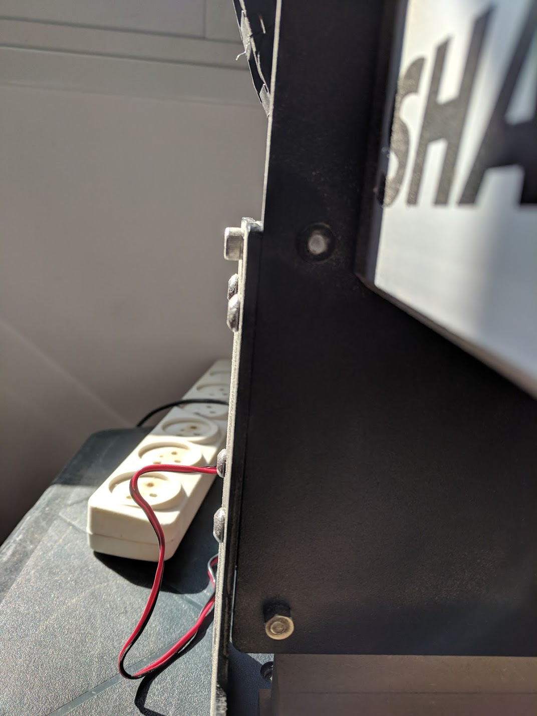
If I rock the spindle mount, there’s some play but it’s really small, see if you can see that in this video. Should I shim it until it has zero play? How do I know the direction to shim (lift the mount or get it stable at the lower position)?
If I take the X to the back, the gap switches sides. I guess this means the Y rails aren’t parallel to each other? It’s weird because if I measure the distance between Y rails at the front of the machine and compare that to the back, it’s less than 0.5mm.
I believe that they’re parallel, but not at right angles to the end plates. So long as the gantry is at right angles to the Y-axis, the machine will still run true. Here’s the canned response from support:
That last 0.5mm is about 1/40th of a degree — probably to take it out you’ll have to do one or more of the following:
clear the powder coat out of the holes
drill out / enlarge the holes to allow for adjustment of the plates
I’m not saying it is loose, the ridges on your waste board being deeper in front or the back can indicate it is out of square to the gantry.
So if grooves are deeper in front of your pass left to right then you would shim behind the bottom portion of your spindle mount.
Put a speed square on top of spindle holder and check it is square/90 degrees to the z plate.