Cadance Manufacturing has a 1/4" bit that has 1.5" Depth of cut and the top is relieved to get up to 2" of depth.
1 Like
That’s the bit I used. I didn’t want to push it on the 2”. The shaft didn’t look relieved that much but it probably would have worked.
So are you happy with the bit. I have the groovee jenny 60 degree down cut bit and it works fantastically. Thinking about getting the 1/4" one.
I have a Melin 4" OAL bit and it works fine but due to its long length it vibrates a lot and I have to pause and check the collet tightness. It has a 1.5" cutting length. Additionally when it starts up it can be out of round and has a distinctive sound. I just stop it and remove the bit and reinsert it… I usually try to seat the bit all the way up and pull it back down about a 1/4" to get the least amount of runout and vibration. Just wondering of the 3" OAL of the 1/4" bit has any of those problems.
If you’re running something with an ER11 or ER20 collet I’ve found that the vibrations are much less worrying and I can push higher feedrates with an 8mm cutter over the regular 1/4" shank. I now buy up / down and compression cutters from a local supplier in 8mm by preference as they’re not much more expensive and I can run them with greater stickout without getting the “will it snap?” noises.
3 Likes
This was the first time I used that bit. I am super impressed with the surface on the insides of the bottom and lid to the box. It is very smooth with barely perceptible machine marks only when it was going across grain.
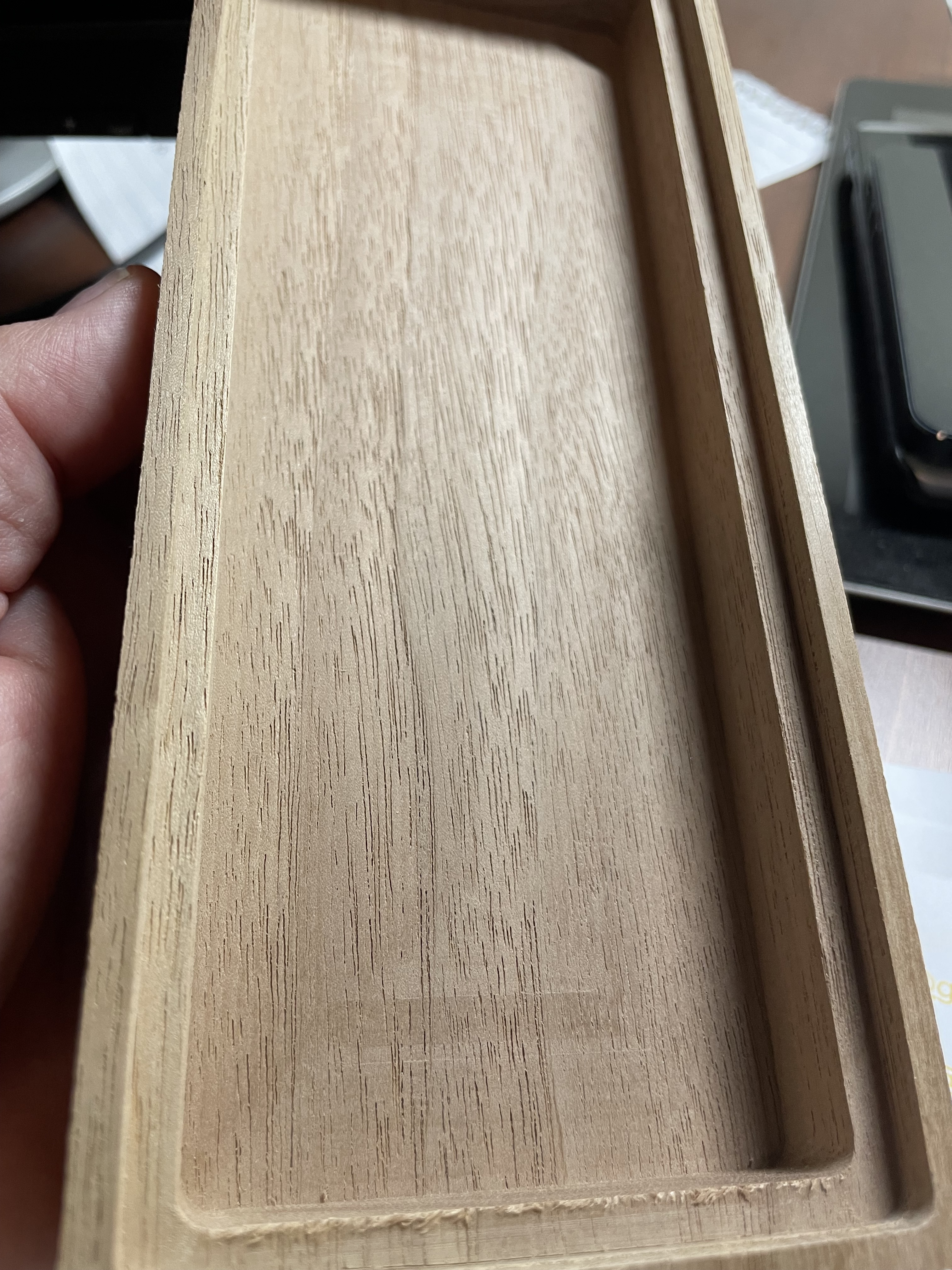
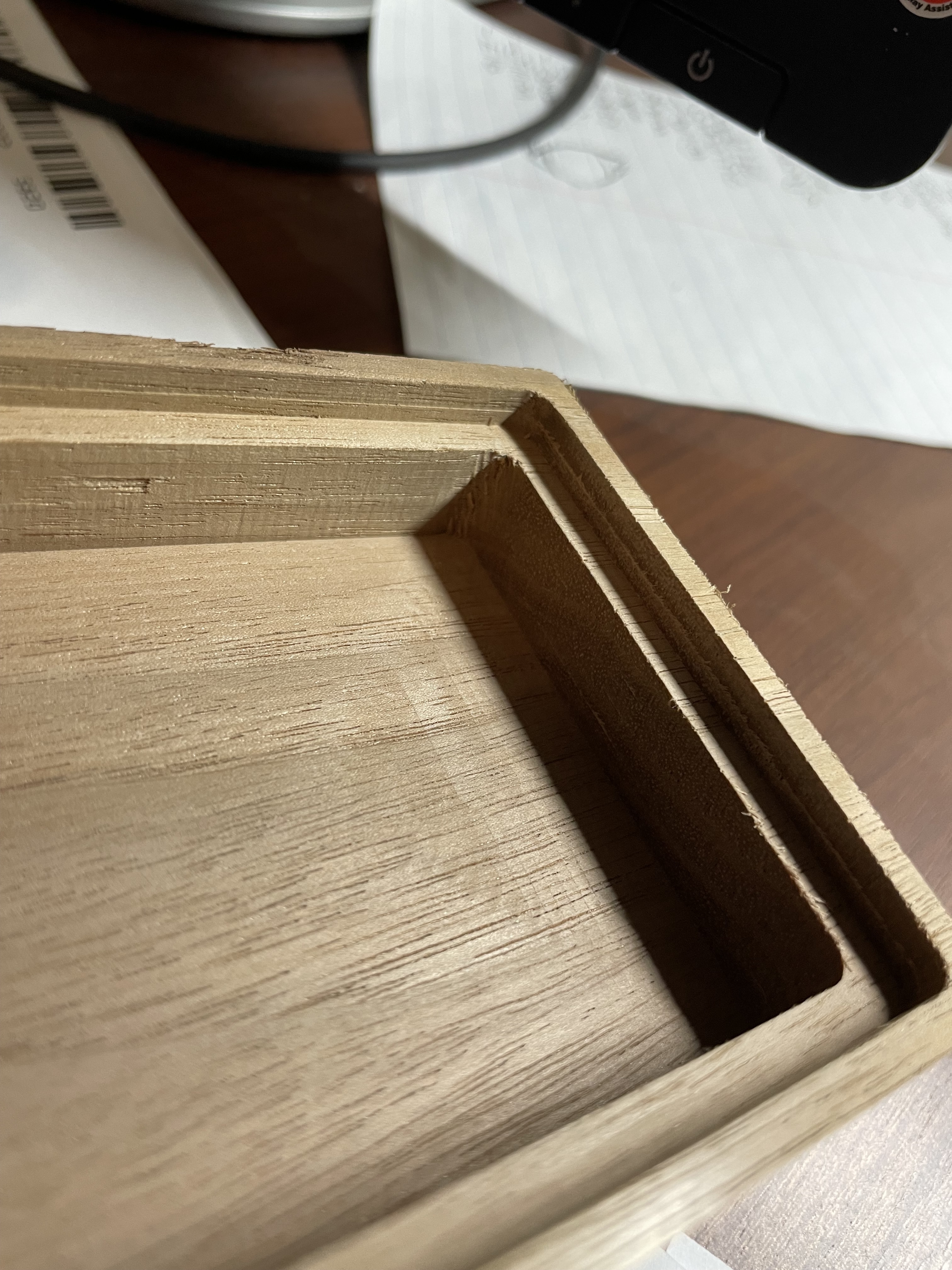
The sides are a little rougher than I had hoped like I mentioned earlier. I haven’t had time to try sanding yet to see what I get.

I have several Cadence bits and like them a lot. I have this one, a couple of V bits in various sizes and their normal Jenny downcut as well as Slim Jen which is one of my favorites.
I have been on the fence on the ER11 collets. Maybe I will give them a try.
I can’t remember if it was this thread or another where I mentioned that I just replaced the router due to bearing issues. This was my first project after that replacement and retramming (although I have not resurfaced yet, just surfaced the project board).
I also bought the rebuild kit including armature and will give replacing the old one a try when time permits.
2 Likes
So, I had a great weekend of learning with the Shapeoko 5 Pro! As promised in my previous update, I cut out a self-standing shelf I’ve been planning in Fusion 360.
I loved the whole work-flow, to be honest.
I modeled it up, checked renders and tweaked things to my liking. Then, I exported the model to a USDT file, which I then sent to my iPhone where I could open it up and “place” the 3D model in my house to get a feel for the size in AR. So cool to be able to walk around the shelves. It really feels natural.
Next, I moved all the pieces into position on a modeled sheet of plywood – actually two 4’x4’ half-sheets.
From here I can switch to the Manufacturing tab for CAM work. The first sheet I spec’ed out these tool-paths:
- Drilling
- 2D Pockets
- 2D Contour (cutting out the pieces except for tabs)
The second sheet:
- Drilling
- 2D Pockets
- 2D Contour (cutting out the pieces except for tabs)
— change tool to a 1/4" 45° chamfer mill — - Chamfer around my drilled holes to allow for counter-sunk M5 bolts.
Now, it was a mistake to do the 2D contour before doing the chamfers, because the chamfer motion just broke the part free from the tabs resulting in little-to-no chamfer on some of these holes. Live and learn and, fortunately, easy to fix “manually”. I was trying to avoid 2 tool changes, by doing it at the last step, but, that’s just silly, because, I am unlikely to start my next project with a chamfer bit anyway, so I saved nothing.
Next came some sanding and putting a slight round on all the edges with my sander. Came out really nice! Much better than I had hoped for my first real project.

Please excuse the mess… and the British monarch in the background, lol.
The whole thing is standing on a lazy-suzan I made years ago (not shown here).
Questions/Observations
-
Why does Fusion 360 require me to model “mickey-mouse ears”/“dog-bones”? This really feels like a missing feature in the CAM tab. They’re not hard to model, but I feel like it breaks the veil between modeling and machining. I shouldn’t have to embed details of my cutting tool into my modeling. It should exist only in CAM tool paths, IMHO. Does CC do this any better?
-
Relatedly, due to the less-than-desirable size of the dog-bones I needed to cut to get things to fit correctly, I’m considering changing my tool to a 1/8" cutter (down from 1/4" cutter) if I cut this again. Does anyone here think this is a bad idea?
-
I learned the hard way on this project that my table isn’t level. It bulges up about 6mm (!) in the center. Since my tool clearance for non-cutting moves was only 5mm above the stock, I wasted a whole 4’x4’ sheet by scarring the top surface up between drilling moves =(. Easy to “fix” by adding more clearance in the tool heights, but obviously, I need to shorten the center 4"x6" posts holding up the center of my table. Ugh, what a chore that’ll be. Level your tables, folks!
-
For fixing the plywood stock to the waste board, I just bolted it and a cheaper sheet of 1/4" flooring board underneath it directly to the square nuts that go into the waste-board slots. I had to buy some longer bolts though. I wish there was some way to use normal wood working clamps. Is there a better way to affix a whole half-sheet of plywood?
-
For this job I used a Yunico 1/4", 2-flute compression mill. I don’t think I had the feeds and speeds dialed-in very well. It was making dust, not chips, but when I speed up the feeds it was making unnatural noises. I originally was using 18000 rpms and 90 in/min, but ended up slowing it down (too much) to 10000 rpms and 30 in/min. I suspect I should probably do something like 15000 rpms and 60 in/min? Max depth for any operation was 5 mm. Any recommendations here for pine 1/2" plywood?
4 Likes
For 1. see:
1 Like
On the dog bones, they’re a burden to bear in most packages, most CAM tools err on the side of not cutting away anything that is in the ‘final model’ rather than hacking out chunks of the model to get into a corner. I normally make a second pass with a 1/8" cutter to clean up the corners a bit and then finish with a chisel (or round off the corners of the mating piece.
As for the chamfer, it depends how you’re modelling them in Fusion there’s a couple of major options;
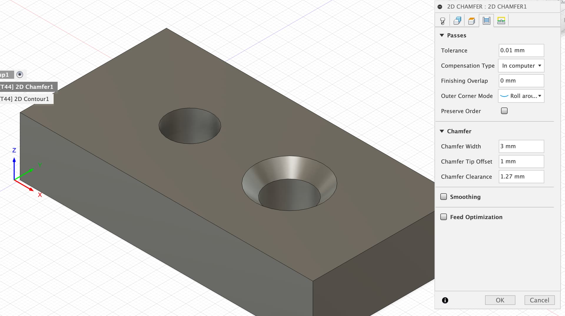
- Do the chamfer in CAM, do not model it on the object, if you choose this then you use the 2D chamfer toolpath and the tool will plunge in and rip round your chamfer at scary speed, sounds like this may have been your first experience. My first suggestion would be, if you’re doing chamfered holes, to reduce the cutting feedrate as the outside edge of a tight circle has a way higher effective cutting speed. I do not use this option at all, and especially not in metals.
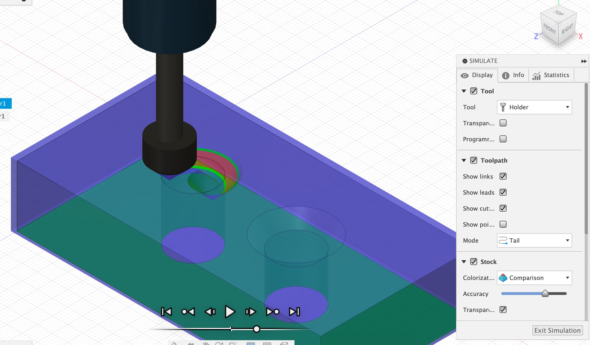
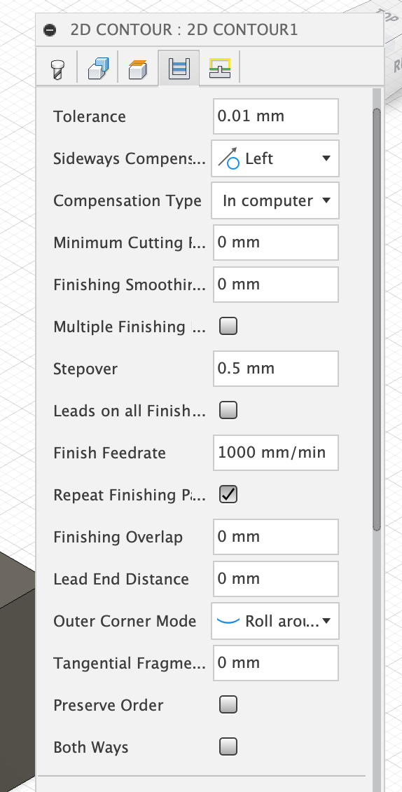
Toolpath setup like this
Cuts like this
- Model the chamfer in the CAD and then use the 2D Contour toolpath in CAM. This gives a load more options about how to machine the chamfer and lets you do it in several passes with repeat finishing passes and all the other civilised options.
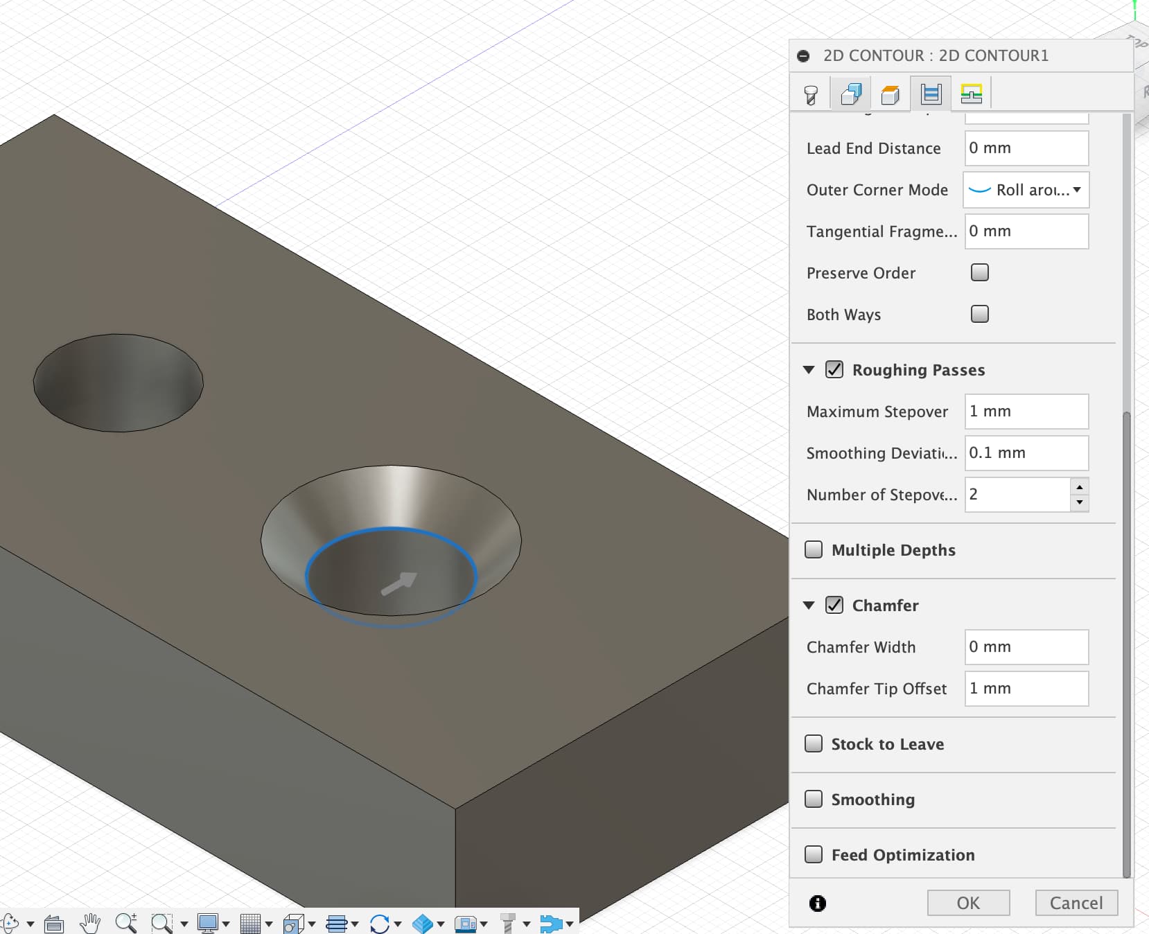
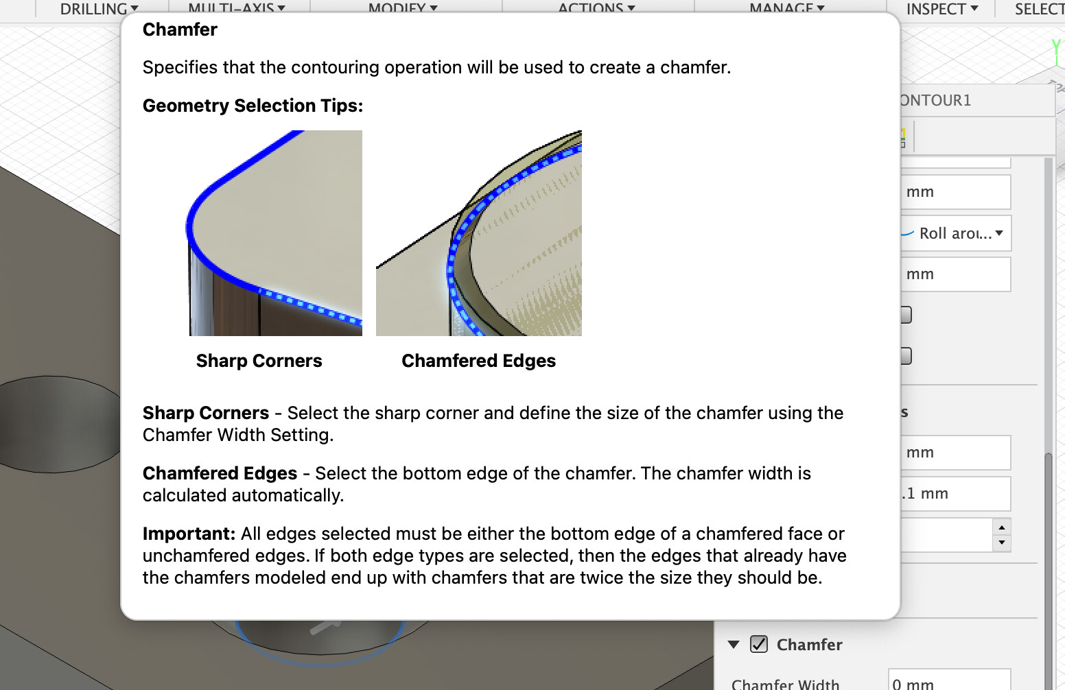
The help for the chamfer function is quite sensible, you can either select the top contour and tell the CAM how wide a chamfer to cut (like option 1 and the chamfer toolpath) or you can select the bottom edge of the chamfer and the machine works out the width.
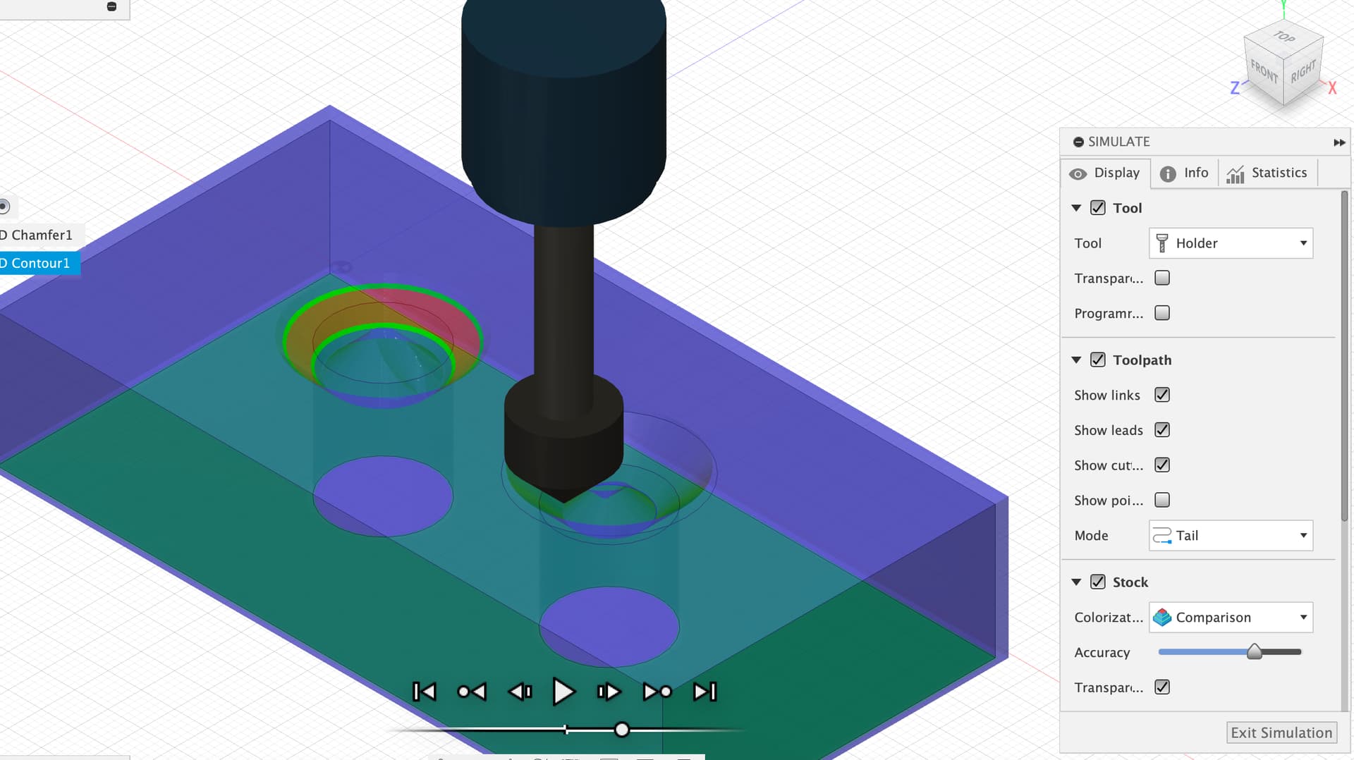
The key tools you get here are the chamfter tip offset which lets you drop the tip of the cutter (which has near zero speed and doesn’t cut well) past the edge of the material and the roughing passes / finishing passes setup. Here I’ve selected 2 stepovers of 1mm each before doing the final finishing pass.
That results in a cut like this
Whichever method, I almost always run a ‘repeat finishing pass’ and set the finishing feedrate down from the roughing feedrate to get a clean finish, it may take longer on the machine but I trade that for the time saved manually sanding and finishing.
HTH
3 Likes
Here is a plugin for generating dogbones in Fusion360. Nifty Dogbone for Autodesk® Fusion 360™ | Fusion 360 | Autodesk App Store
I have never used it, but it may do the trick.
1 Like
Excellent! Thank you.
FlatFab looks really cool. Thanks. you!
I modeled my chamfers. But man, you’re so helpful! This is all great stuff!
1 Like
This topic was automatically closed 30 days after the last reply. New replies are no longer allowed.