First, I connected the extrusions with two piece of 40X80/3 U shaped hard aluminium extrusions on the bottom of the machine.
Secondly, instead of using the stock steel frame I made my own pieces to connect the extrusion bed with the rails. I used 60x20 flat bars and made them 130 long. I should have made these a bit longer IOT use a good quality precision vise later…
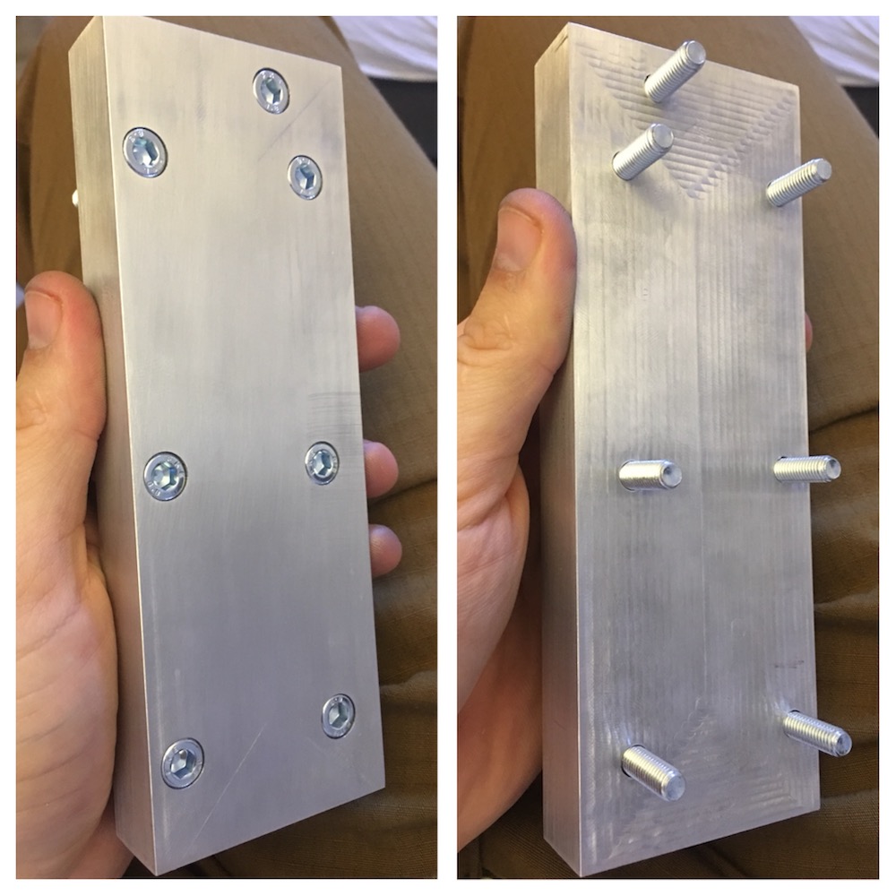
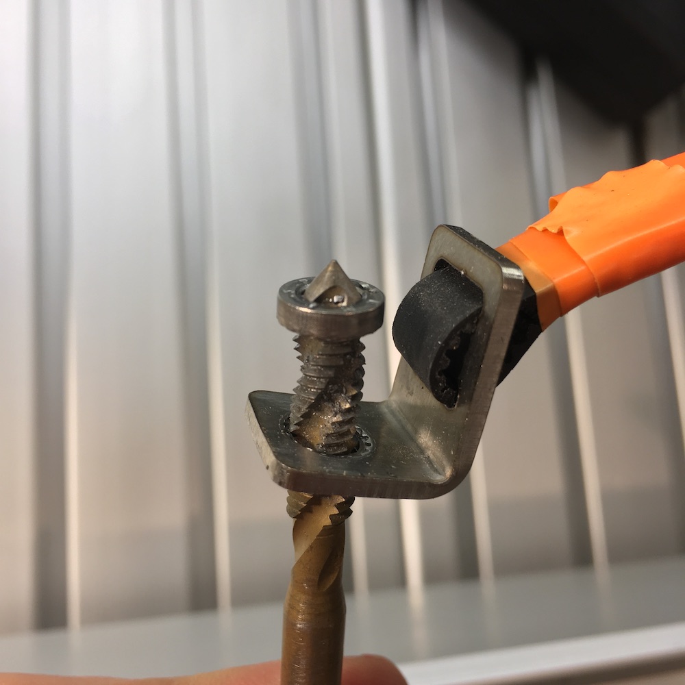
Then I messed up enlarging the M5 threads to M6. (Yes I have predrilled

Than I assembled the whole thing and ended up with a thing that was lacking the usual 3 things, parallel, square and perpendicular…
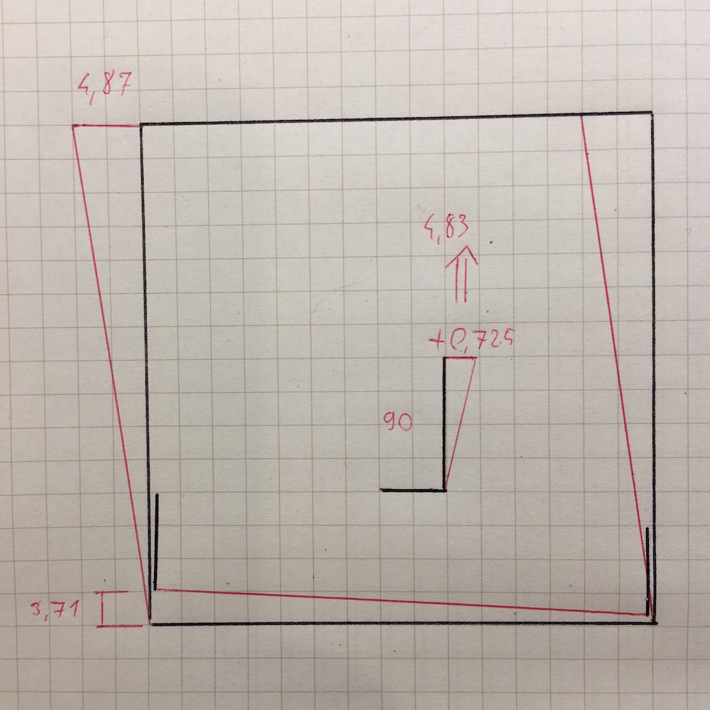
Unfortunately the rails were cut inaccurately. None of the four end were square and all were differently inaccurate.
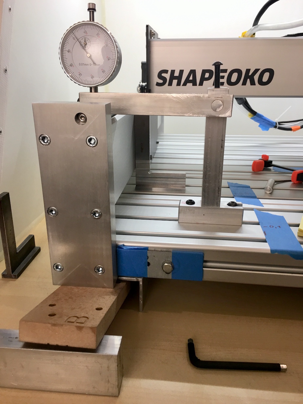
Than I tried adjusting and shimming all corners. First I picked random points along the rails to lift and tap it to position but that did not work.
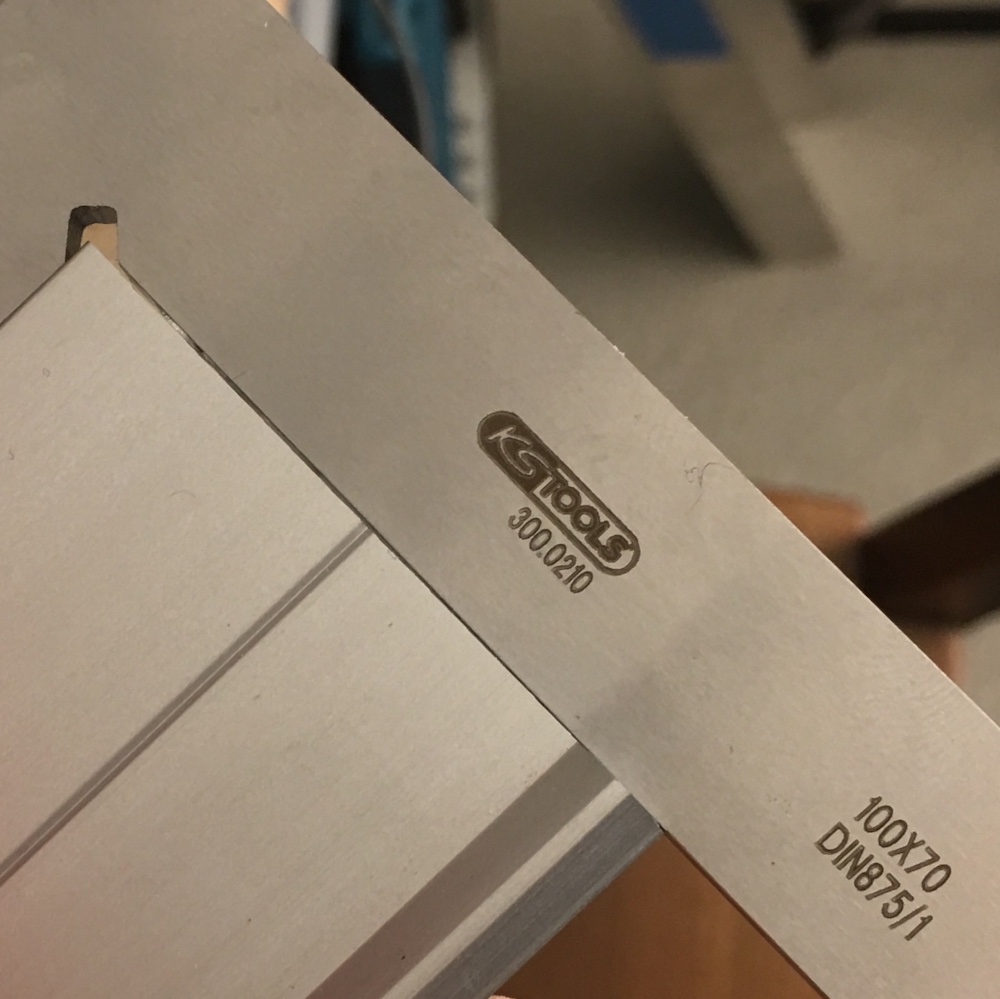
Than I started from one corner and work my way around with wedging the legs into the desired position with a piece of scrap MDF, which worked really well. I was checking the height and perpendicularity continuously.
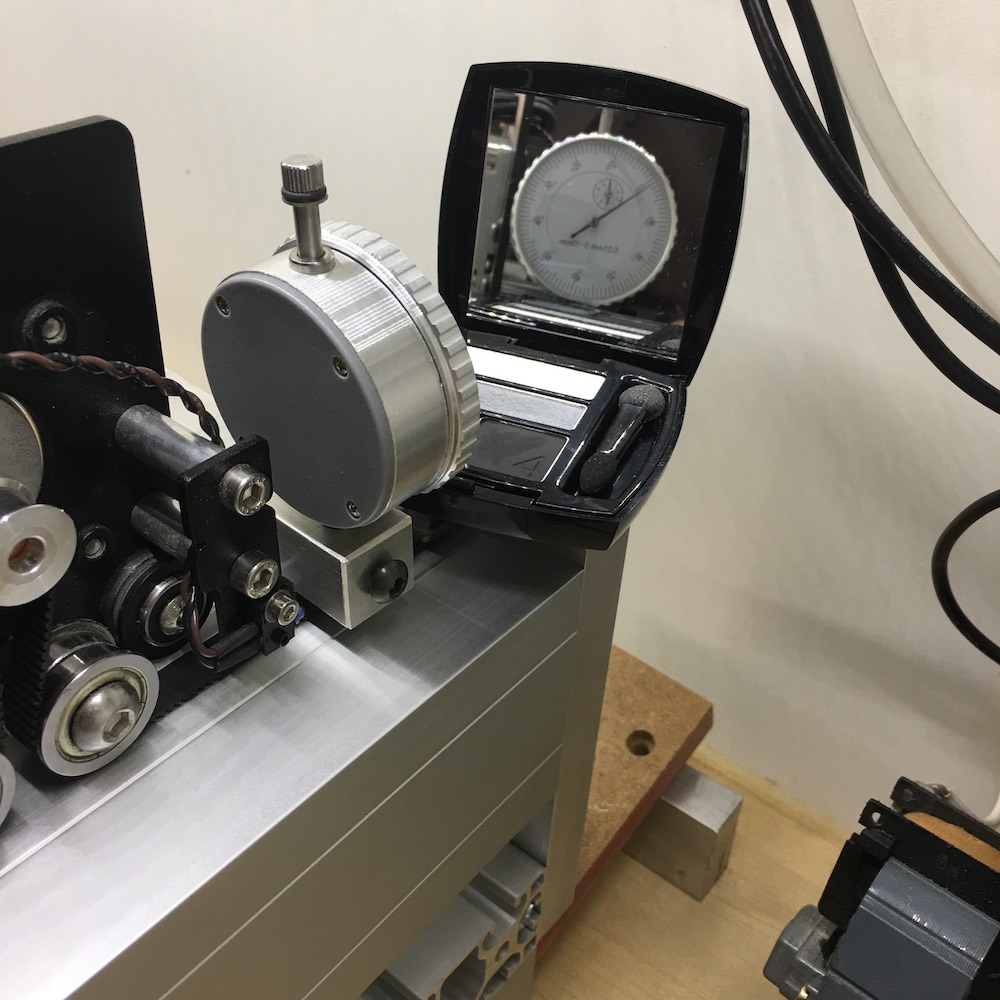
Did the same process with my wife’s makeup mirror on the backside.
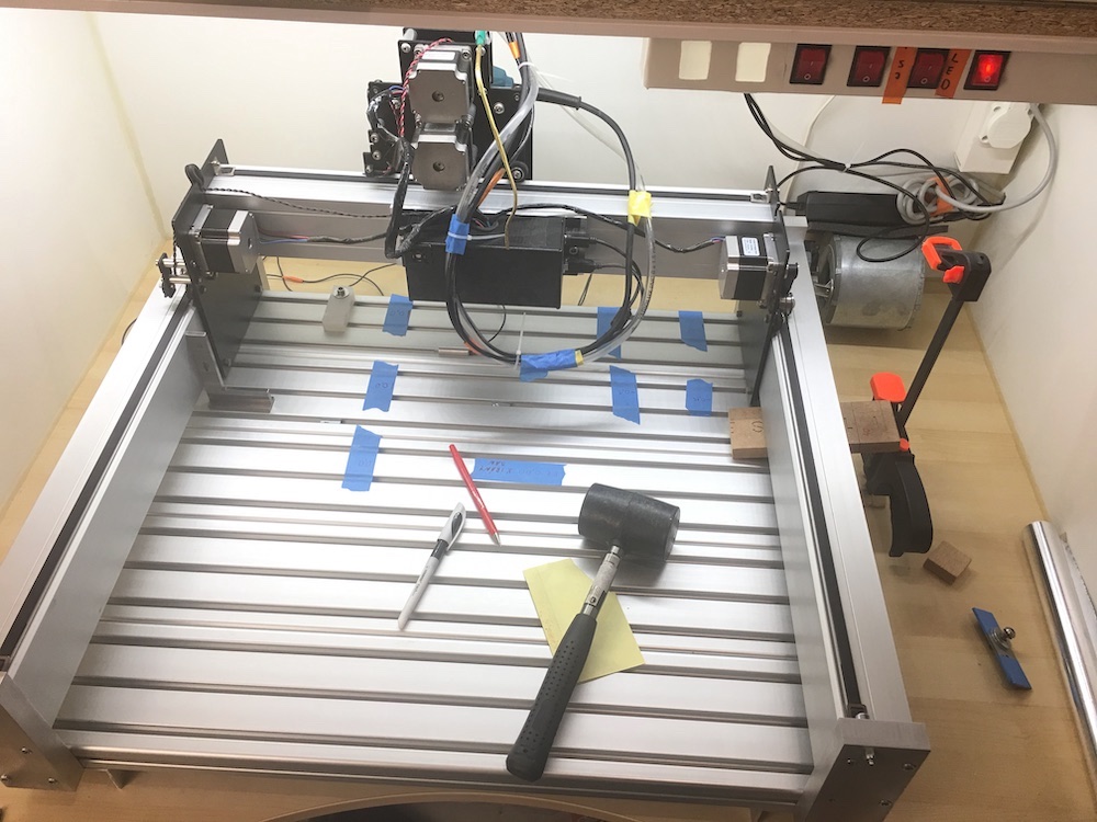
In the end I confirmed parallelism with “closing a circuit method” (see the red LED in the corner).

The machine is still not perfect but close enough for what I use it for at the moment. I usually make soft yaws anyway which solves most of the leftover inaccuracies. The next thing I am planning is to make a piece that helps tramming. I have already seen the CAD of that on the forum)