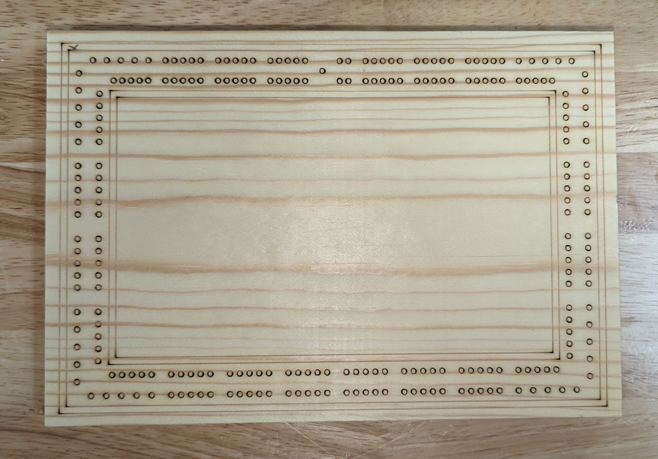
I am really struggling with a recent issue I’m having. I have made literally hundreds of cribbage boards using a combination of laser engraving and CNC where everything has lined up fine. Recently, I’m seeing issues where the machine seems to be starting too far left and down and I need to actually move the 0,0 over manually to the right to compensate before drilling. Any ideas what could be causing this?
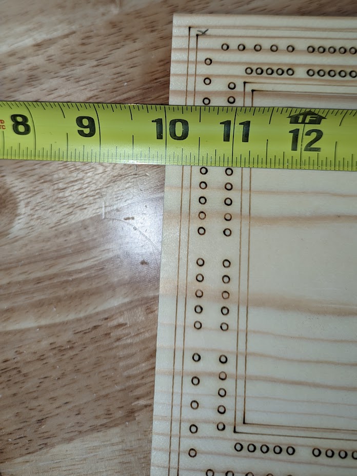
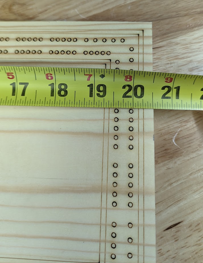
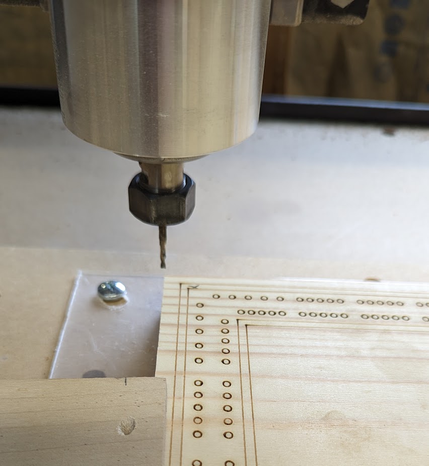
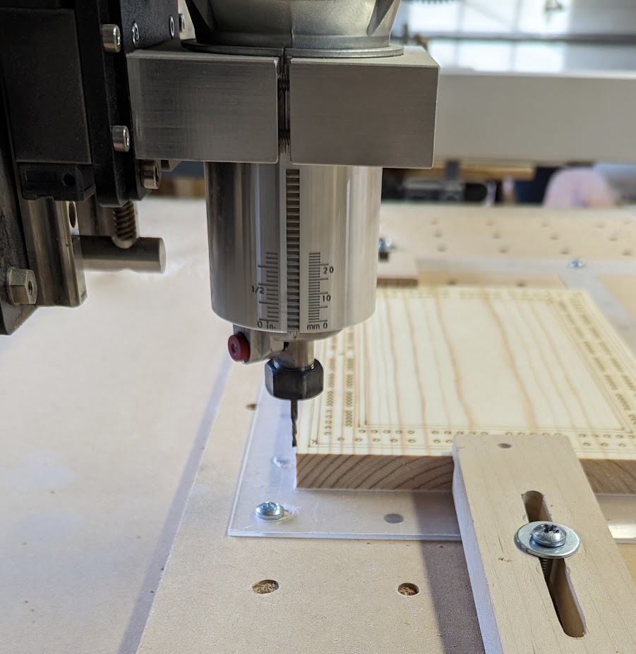
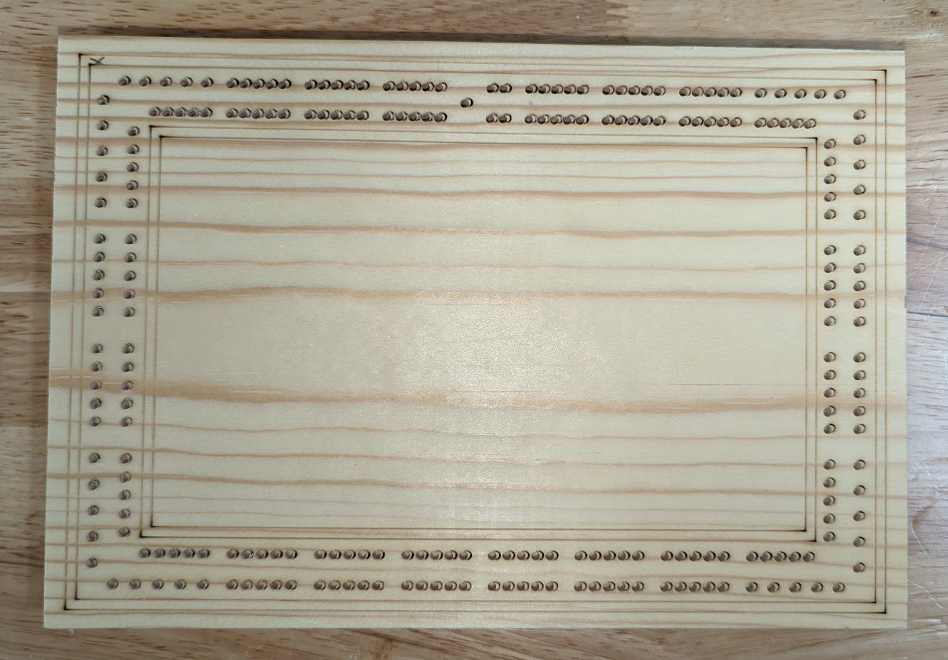
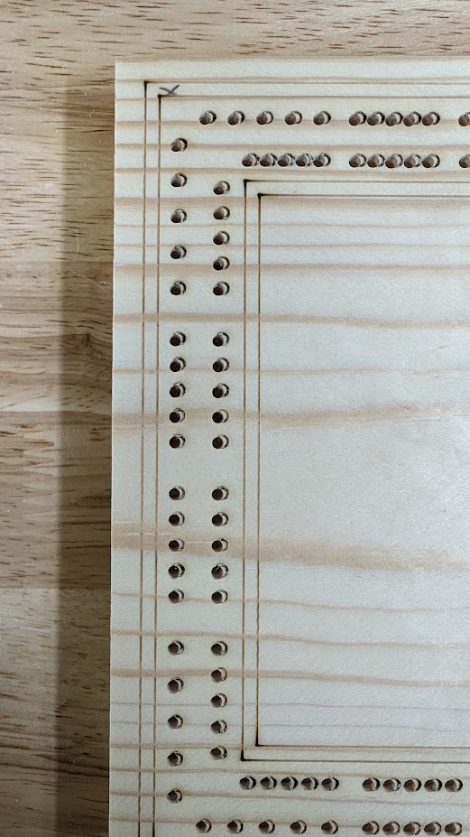
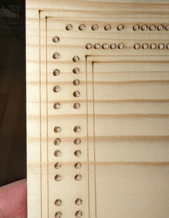
Here are some pictures showing the laser engrave, the 0,0 on the CNC, and how it is drilling too far left and down.
Yes, want the drilling of holes to be aligned with the laser engraving.
Process is as follows:
Create DXF of item to be engraved and drilled in Vcarve. Set 0,0 to top left.
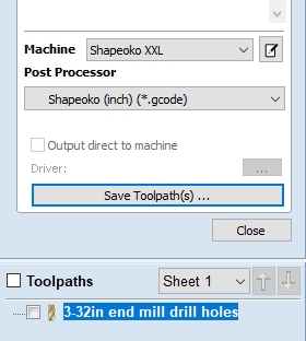
Use DXF in Vcarve to create toolpaths for Shapeoko.
Import DXF to engraving program. Add items to be engraved on laser, set 0,0 to top left. Save engraving to 200DPI image.
Engrave image with laser. Move item to CNC. Drill holes with CNC.
This process has worked to produce literally thousands of pieces where the alignment is spot on. Only recently (December timeframe) did the mis-alignment start to show.
One thing that did happen was my router cord got stuck on a hold down piece, causing the gantry to grind and I think knock it out of square. I posted earlier about that, and found the fix to be sliding the x axis all the way to the front and re-initializing. This took care of my being out 1/8" from side to side and the machine is square again.
Any help or things to try and re-test would be greatly appreciated. I’m at my wits end here, and production is basically stopped dead in the water until I can resolve this.
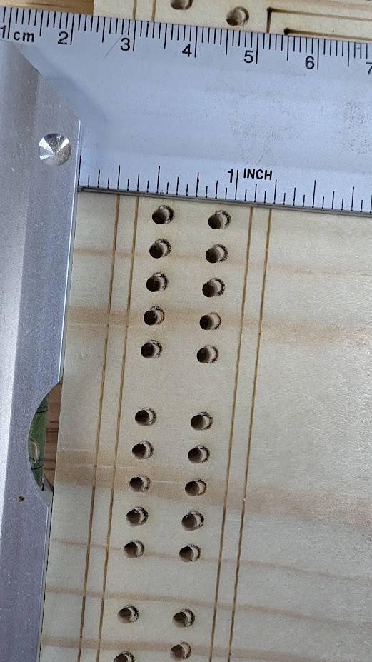
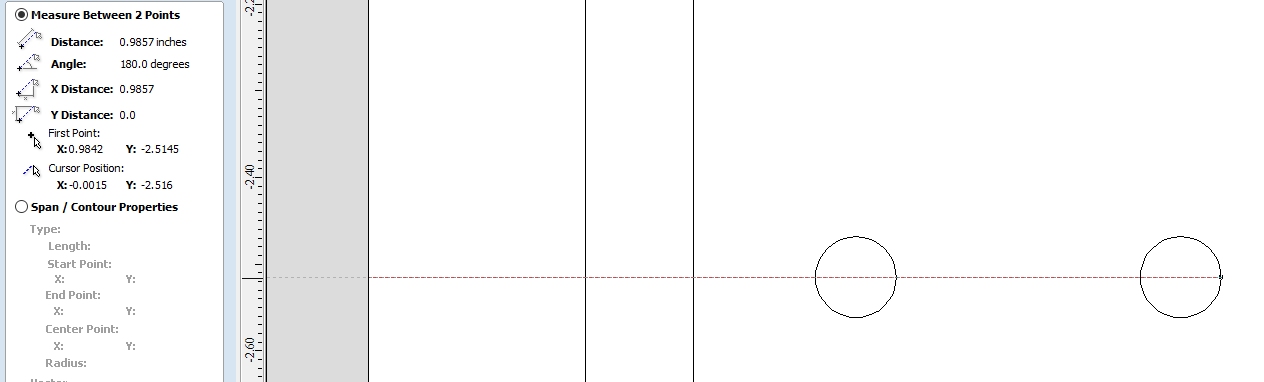
Thanks. I’ve actually done that as well, and noted the same issue. My initial thought was that the laser was off, but after measuring each lasered piece, they are all right on to spec. The picture showing the close up of the square above shows it pretty good. The outside of the first line lasered is supposed to be at .25", which is right on. The outside of the inner hole is supposed to be at .98", which on the lasered piece, it was. But on the CNC drilled piece, it is closer to .875".
In continued research I found info on how to check V-wheels and belt tension. I re-tensioned the belts and adjusted three v-wheels that were not spinning, and it seems to have made things quite a bit better, but still off by about 1/16" over and down. In reading some more, seems that people talk about doing a GRBL test and seeing if your steps are off. Is that something that could possible help resolve? Would slowing down the speed of the axes potentially help?
Just curious, Are you taking zero on both machines by eye?
Also if it goes to plan, do you still see the circle you engraved after the hole is drilled?
The laser is zeroed and has a fixed jig in place to keep everything at 0,0. The CNC also has a fixed jig, and each starting piece of a run is zeroed out using BitZero. Subsequent pieces in the run are then drilled knowing that 0,0 has been set.
In the past, when tested, this method would have the drilled holes be right in the center of the engraved holes, wiping them out completely. I use that only for calibration. When doing production runs, I do not engrave the hole locations.
ok got it. sounds like you’re doing everything right. and since you said it’s worked in the past without any issues, that makes me lean towards something being worn out or loose.
That was kind of my thought. Just not exactly sure on where to go beyond squaring the machine, tightening the belts and adjusting the v-wheels. Have never messed with any of the GRBL steps things I’ve seen some videos on, and I don’t know how that would impact the left/right, up/down starting point of the machine.
I’ve never messed with those parameters either. I would think if they are out then 1" of movement isn’t really 1" and calibrating would definitely help. Of course you would have to re-do your zero’s
I’m sorry Tim, I’m sure you are tired of a million questions but I have one in respect to the BitZero. Did you use a pin or an end mill during the X and Y routine?
On the first set of a run, I use the pin that came with the BitZero, then switch to my end mill. I know sometimes, if the flute is not perfectly round, you may have slight X,Y, inconsistencies. Good thought though!
Pretty sure that just means your zero is off. There are a lot of factors that can influence the result of probing when you’re looking for that level of precision and accuracy. You might try milling a 1/4" hole in your jig and using that with the 1/4" pin in your spindle to establish zero.
I have found that even the way to clamp in the material has an effect. If you used more force one time than another, it can be different.
How was your material cut to-size? If I have a piece of material that is already to-size (unless cut on the CNC to exact size, not “table saw” to-size), I always use the center of stock found by the diagonals. In this case I would use the center for both the laser and CNC operations.
I would be more inclined to believe these to be potential factors if I haven’t already produced more than a thousand pieces with this machine, using the same exact process, and now am experiencing different results. Something is most definitely off with the CNC. A top left 0,0 is very easy to accomplish, as I use all square cornered stock, and when doing a top-left 0,0, even if your right side is off by 1/32" or less (which is typical for my cuts using the miter saw) it doesn’t impact start point of the CNC.
Appreciate you responding and offering some advice, but unfortunately, don’t think it applies to my situation.