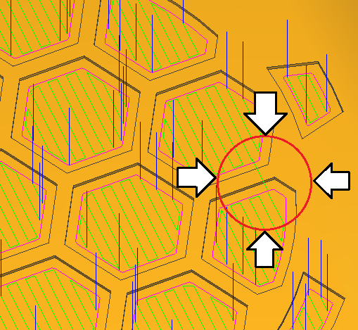
On Meshcam Build 27. When generating the path you can see how here the tool don’t go completely up.
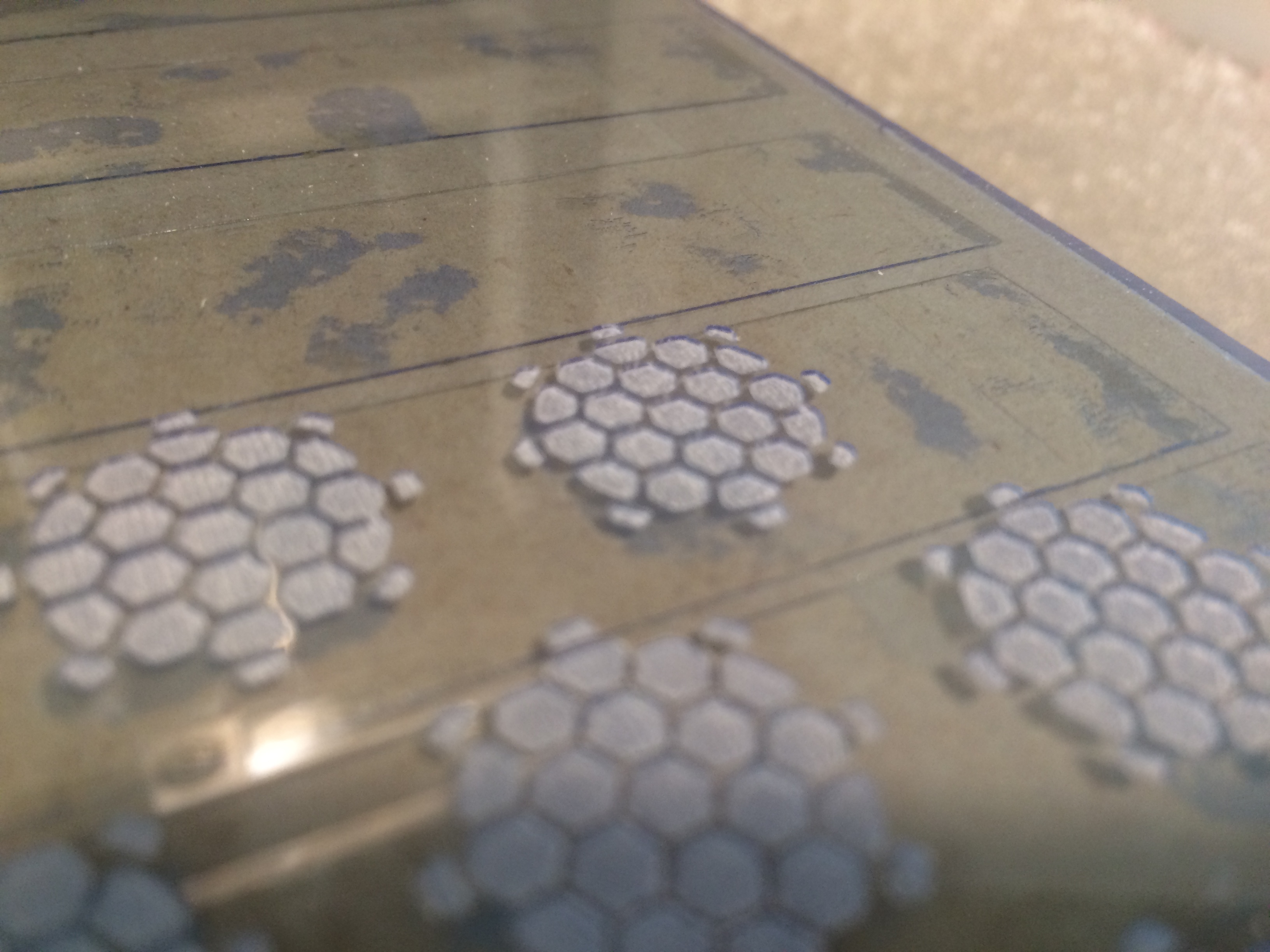
Because of this, as you can see on this picture, since I’m milling 0,1mm depth with a 0,5 diameter mill and the surface is complicated to set perfectly to 0. When doing the movement showed on the previous picture I get the result shown on this picture (two upper shapes).
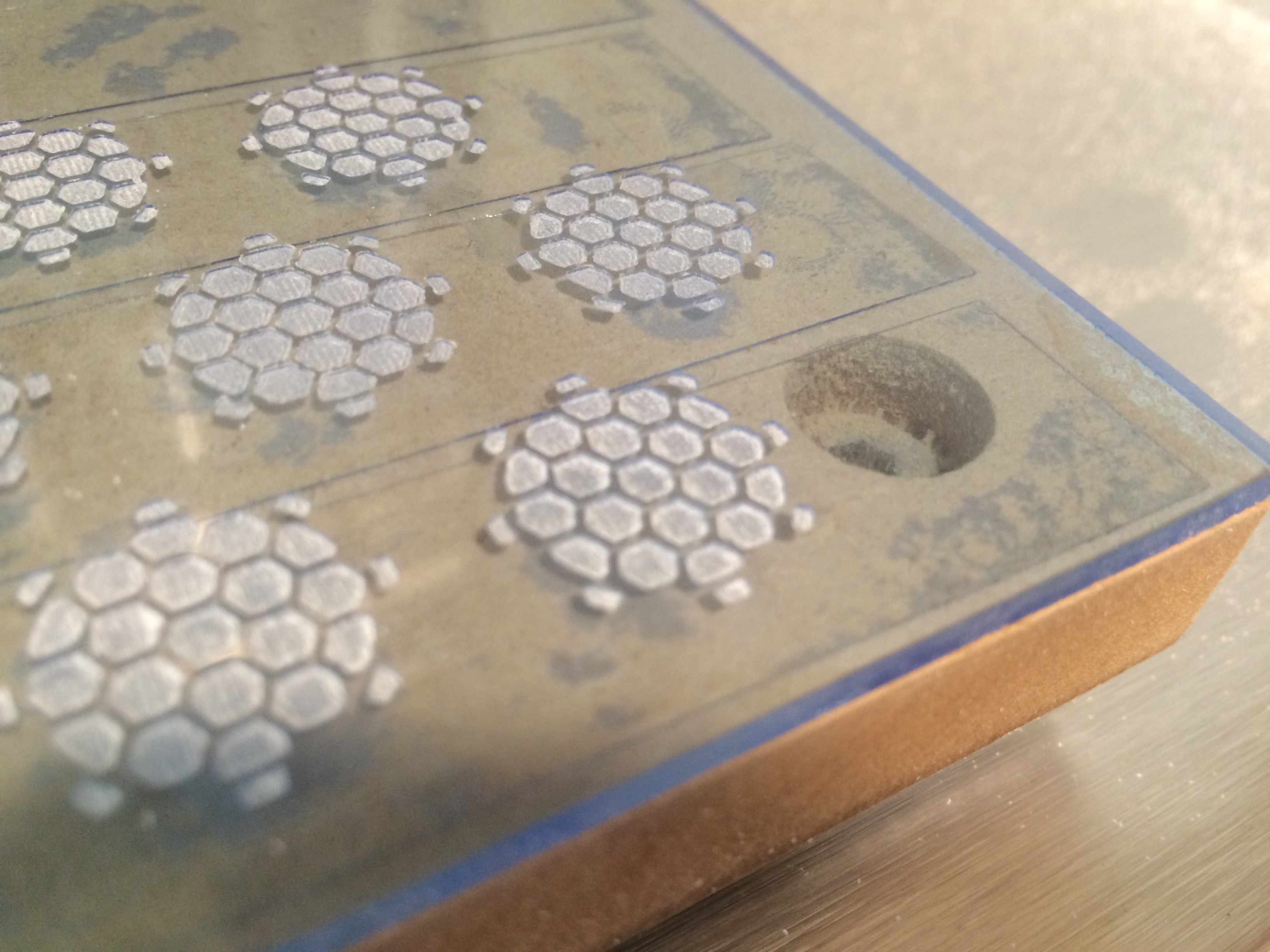
Otherwise on this picture you can see some of them without the same problem. I’ve tried to generate it along X, along Y, X and Y, and the result is similar I just change the position of the problem.
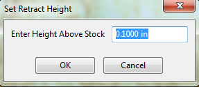
The problem is that instead of going up the “retrait height” it just go up 0.1mm (the engrave depth) and since the zero on Z axis is a little bit lower that real 0 of the surface it mill the surface of the plate.
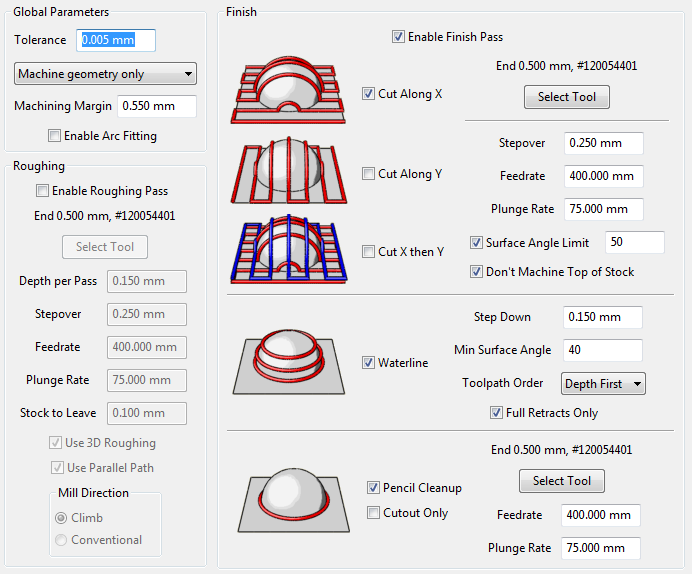
@david, you have “Do not machine top of stock” checked but that only means MeshCAM will not purposely machine the whole surface. But at any time MC might put a toolpath right on the surface as in your case.
You might try changing the parallel finishing stepover just very slightly (1 or 2 percent) and see if the surface toolpath goes away. There is probably some kind of internal interaction between the projected toolpath and the pocket outline that is causing this.
since the zero on Z axis is a little bit lower that real 0 of the surface
If you want to guarantee no tool marks on the surface, you should do this the other way around. Make the recesses .20mm deep, and zero the cutter so the actual surface is .10mm below the “virtual” surface. I have done this in the past where the top surface was polished and I wanted to avoid it entirely.
yeah, I’ve seen this same thing before, it’s only in very very fine layers, the cutter takes of 0.1 or so more than it should in the odd spot. Sorry no idea how to fix it, i just tried to sand it out.
Finally I did what you say, I make the 3D model engrave deeper (from 0,1mm to 0,3mm), then I offset the Z (zero coordinate) 0,2mm upwards of the material surface, and changed the parameter “step down” to 0,3mm, so I was engraving just the 0,1mm.
It works, but don’t look to be the best way of working, looks like a failure of the software.
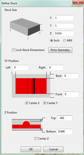
This is what I do to my Z Stock setting to ensure the top of my stock does not get any machining operations,
Set the top to a very small negative number.