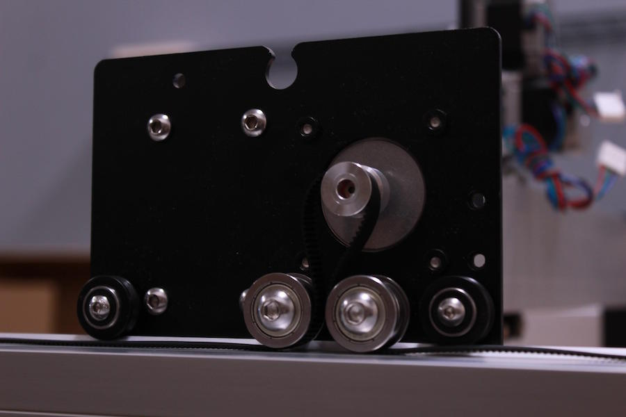
Trying to isolate the issue with my Shapeoko, I was examining the different components for any slop or break when I focused on the Y Axis Carriage plates.
Some people have turned them to get more accessible surface area on the wasteboard but I wondered if anyone has ever considered redesigning the plates so the stepper were repositioned to face the X rail instead of being behind or alternatively in front. The Y plate would become effectively two narrower plates facing each other, one that attaches to the X rail with the V wheels and the second, attached to the first with a pair of brackets would have the stepper and gears facing the other direction. As a result, the surface area would be increased by approximately 2 1/4 to 2 1/2 inches with the same rails.
Maybe there are reasons why this would not work but I found this an interesting possibility. Unfortunately, I don’t think that I have the required mechanical and electronic engineering skills to try it by myself.
People have done it (you just need motor spacers) but it’s not standard configuration.
One of the nice things about the Shapeoko in the stock config is that you have router overhang - this can be used to engrave items like chopping boards or make dovetails. It’s very useful to have in the back pocket.
I don’t understand why you would lose the overhang at the front as the Y plate would be the same size at the front but smaller in the back; I’m not talking about inverting the Y plates. The Y plate would be about the same width as the X rail thus 2 1/4in narrower so it could move further to the back.
That’s an interesting idea and could work, but you lose a bit of mechanical advantage (shorter plate, shorter lever arm to keep the Y rail from twisting against the V wheels). I don’t know if it would make a difference, but (just guesstimating) be doubling up the force on the wheels. That’s what’s cool with this machine, lots of ways to skin a cat.
Yes I thought of the loss of mechanical advantage and this was one of the reasons I wasn’t sure if it would be possible but on the other hand, I thought that maybe if needed, using flat wheels on the outside of the Y rails could compensate for this.
Interesting, when the idea came to me, I was thinking about moving all hardware from current Y plates with a few additional parts beyond the new plates but you’re thinking a significant upgrade. It would certainly increase the stiffness and make a better overall upgrade but would this could also make the upgrade a bit pricey with these two sets of fairly long linear rails required.
So this brings several questions regarding the value proposition for a potential builder, is this for regular users wanting more usable space or for the power users who want it all with a more substantial pocket book.
If useable space is the main goal then imo leave the machine alone and make a bolt on plate that extends off the front. Cheapest simplest easiest way to do it.
Also a benefit of a sub plate is less leveraging on the gantry due to your work being higher. Winston actually made a lift torsion box for cutting his board.
Due to the clearances and keeping the stock drive/motion you wont find an awesome way to make new plates without making them from steel and adding the same style PEM nuts.
You mentioned $$$
A blank 0.500" cast fixture plate (extends to full travel s3) is less than $200 shipped from midwest steel supply. Drill holes, profit
Ohhh man I so wish I knew to use cast fixture plate instead of a regular 6061 plate. Bought 3/8" 2x3ft plate for almost $200 and the height difference back to front was around 1/8". Should work okay after I surface the spoil board but I’m just so disappointed. 1/2" ATP5 plate in the same size is actually cheaper than what i purchased. Always something new to learn every day.
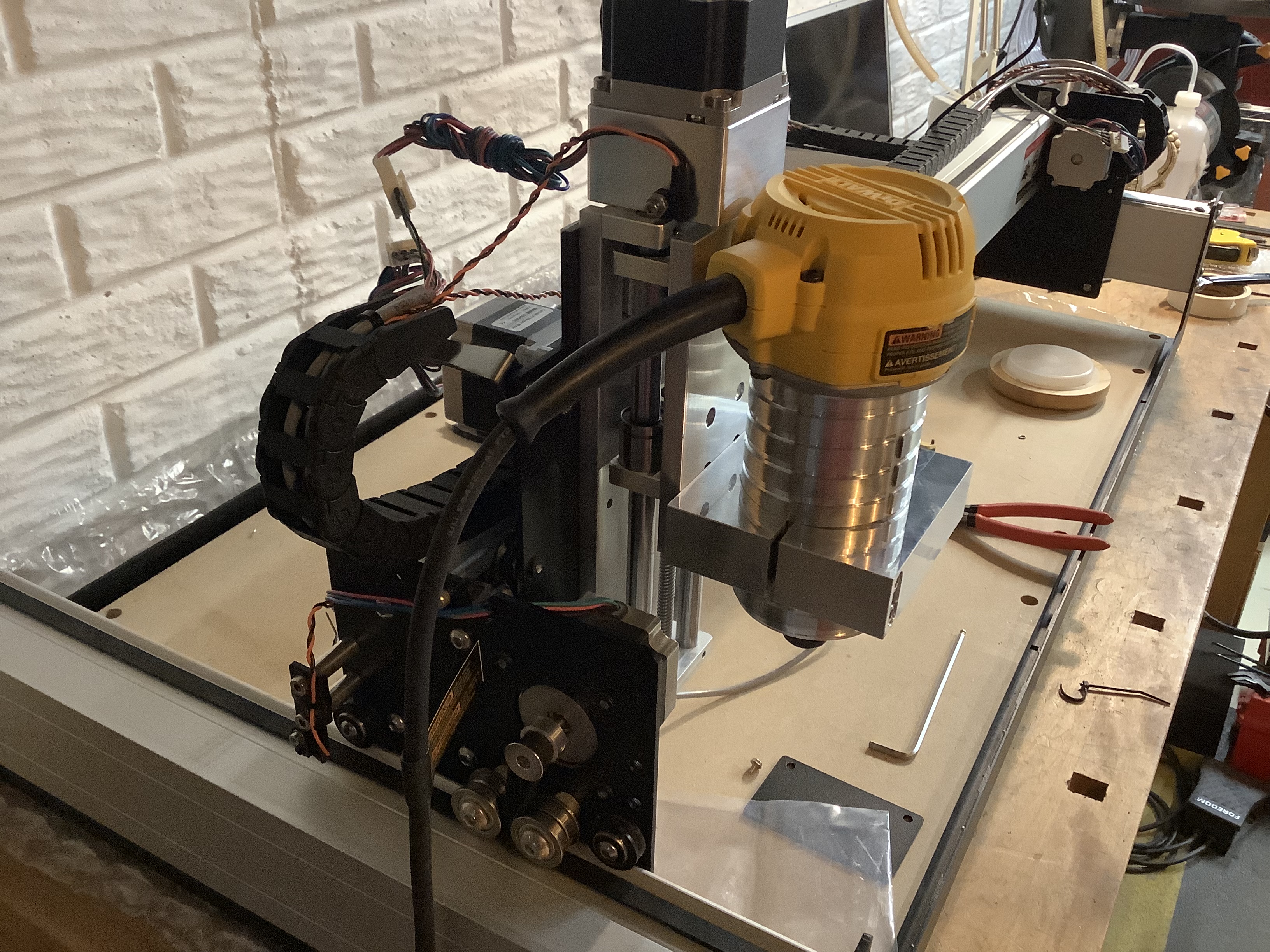
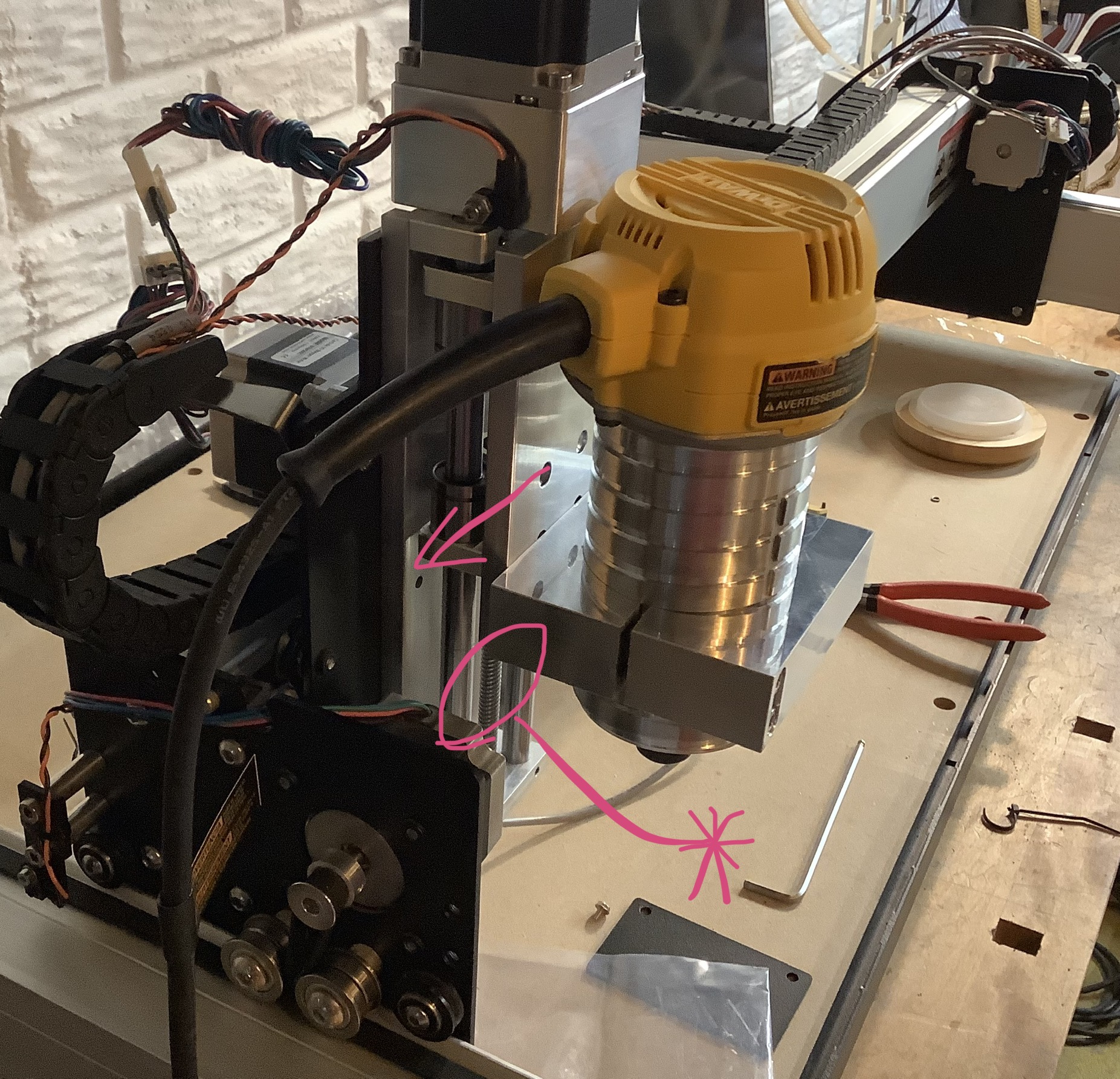
When I bought the upgraded Z Axis, it added a bit of mass, and extended it so far forward I didn’t like how far cantilevered out ahead over the rear V pulleys it hung. So, to reduce the overhang, I was able to eliminate several spacers by dremeling the backside of the Z plate for bolt clearance, grinding the Dewalts plastic instead of shimming it out, and then inverted my Y plates (positioning the rearward motors ahead of the gantry instead of behind it). While this arrangement better supported the Z carriage, and provided a few extra inches of Y travel within the frame of the machine, it also put the Y steppers in the path of collision with the router bracket, costing me an inch and a half off the X travel. So to get that back, I realized the best place to put the Y motors is actually on the outside of the Y plates facing inward.
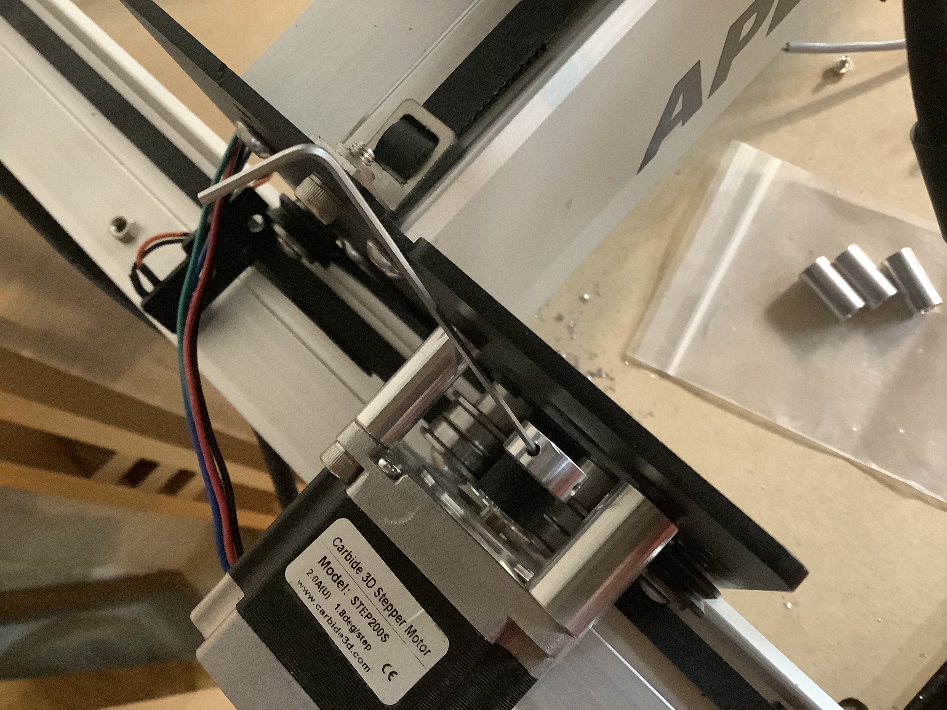
As luck would have it, the upgraded Z Axis freed up enough hardware to do it, and since the motor standoffs from the old Z assembly were designed to do the same thing, everything just works out. It took another couple holes here & there to place the limit switches in their original positions on the new configuration, but after flipping the drive gears round on the motors and some other fiddly cable & harness maneuvering, it ultimately works out to maximize the work envelope and stabilize the heavier Z.
I also opted to use the original stock Z limit switch, and was able to by simply drilling & tapping a couple tiny holes in the top motor mount for fitment.
Not sure what I’m going to do in the software yet to tell it that I’ve changed these dimensions, but I’ll cross that road when I’m done figuring out wiring…
If I understood you correctly, you basically moved the workable space over the wasteboard so you are trading the space you had in front of the frame for space on the wasteboard so the overall accessible work has not changed. I don’t think the software will care except that your south west corner will move inward but you should be able to jog more south.
What I was proposing was to make the plates smaller by about 2 1/4 in and place the motors in front of the X beam. This would give you more space overall without sacrificing the space in front of the frame. Using another GCode sender like CNCjs or UGS where the size is not pre-coded in the app should be able to define the new size.
If I’m reading that right, you’d still run into the issue with moving the motors in front of the X. The big blocky router clamp will overlap the Y motors by about .75” to 1”, so once the Z carriage travels to either end of the X & plunges down, you’ll get a collision. So to prevent that, you’d either have to limit your work envelope by a couple inches in the software limits, or do what I did here and mount your Y motors outboard. UNLESS, I’m just not visualizing what you’re talking about correctly, which is entirely possible.
I’m out on the road, so I can’t tell by looking it it, but perhaps you could tuck your Y motors inside the X beam pointing out, to minimize the plate width… course you’d end up with heat buildup in there, & x Aluminums CTE, your calibration would be a mess. Perhaps on the outside of the X beam, but in line with it facing inward? Or at that point maybe just skip the V rollers altogether and slap a linear bearing down to slide on like Vince suggested. & then at that point just mount your Y motors to the frames end plates, and have them turn a couple ball screws instead & skip the belts too. Shapeoko Pro?
No, I guess I’m not being clear. First, you would need two new Y plates on each side.
If you look at the current Y plates, they have two functions: attaching to the X beam to the Y beam through the V wheels and holding the stepper so it can pull the carriage using the belts. These two functions would be separated and each mounted on two separate plates. The Y steppers on each side of the Shapeoko would move from being inside the frame to the outside similar to what you showed above but instead of staying on the same plate behind the X beam, the steppers would be on a separate plate on the other side of the Y beam. That secondary plate Y plate would be attached with bolts to the new Y plate that is 2 1/4in narrower. As a result, the Y movement would be increased by the 2 1/4in. The stepper plate would also travel on flat wheels down the Y beam and the position of the belt would move toward the middle of the beam.
Cast aluminum plate? When you get it, how do you flattened it for use since it is bigger than the S3? Or do you mount a smaller one on top that you can flatten?
Aluminum Cast Tool & Jig (ATP 5) plate is vertical cast, stress-relieved, machined plate providing sound dimensional stability with minimal or no distortion even after extensive machining operations.
Cast Aluminum Plates have a precision machined surface for superior flatness, flat within .015’’, and +/- .005’’ thickness tolerance, and are protected with PVC plastic on both sides. Cast Aluminum Plate typically has a surface finish of 25 RMS or better. ATP 5 has a tensile strength of 41KSI a Hardness of 70HB and a Yield Strength of 18 KSI.
Cast Tool & Jig Plate ATP 5 is typically stocked in 48.5’’ x 144.5’’, 60.5’’ x 144.5’’ and 72.5’’ x 144.5’’, domestically partnered with Vista Metals out of Fontana CA, our Vista Metals ATP-5™ cast aluminum plate can be produced in custom widths and lengths with a very short lead-time. ATP 5 has outstanding machinability and responds very well in today’s high speed cutting environments. ATP 5 is the preferred choice for engineers that require a dimensional stable product that has great strength to weight ratio. Vista Metals cast aluminum plate (ATP5) is also available in metric thicknesses, in as little as 2-3 weeks lead-time delivered with a minimum order of only 2000 pounds. ATP 5 cast tooling plate applications include, but are not limited to, Computer & Electronics, Pharmaceuticals, Machining fixtures, Drill jigs, Index tables, Semi-Conductor, Automotive Molds.
Standard Cut Tolerance: -0’’ to +1/8’’
Precision cutting (+/- .005’’) available. call for a quote"
Its flat enough to use as a deck as is. You always face fixture plates that are bolted/attached.
Awesome, I wasn’t aware this stuff existed! Midwest Steel is a 20min drive away for me so it looks like I’ll make a drive here within the next month and go pick a piece to use as a baseboard. Then I’ll spend the next 3 hours drilling and tapping holes. Did you do 1/4-20 in yours or larger? Aren’t Mitee-bites 5/16" thread typically?
This might be one of our favorite things that we make. This is a 1/2" thick aluminum replacement table for your Shapeoko Standard 3. It’s got over 90 M6x1 threaded holes to give you plenty of clamping options.
1/2" is a nice thickness, but it’s going to add some serious weight. Also that depth shouldn’t hinder bolts/clamps from clamping down. If you do use long fixtures/clamps ensure you add some space below the plate (standoffs/mounts)