You just switch the left and right connectors until they work the way you want. One already turns “backwards” and the other forward. Switch them and you’ll be fine.
1 Like
Ah, good point, Mike, thank you!
Aren’t you just moving the motor forward, to the other side of the X extrusion? They’d still go the same direction.
They’re not only moved forward, but they’re turned 180-degrees and mounted such that they ride over the tops of the y-extrusions.
1 Like
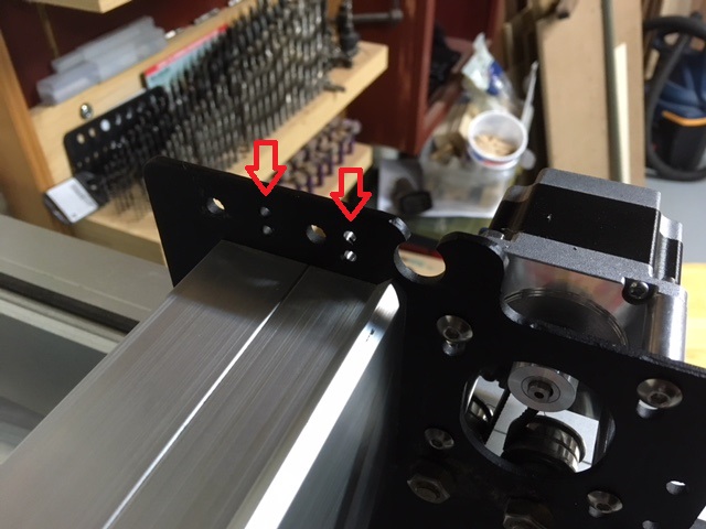
When I started this, I hadn’t realized I would need to drill new holes for the x-axis belt retainers.
So I had things mostly reassembled when I discovered this, and I didn’t want to tear down again.
So I made an alignment block to keep my drill bit positioned correctly, and drilled the new holes with the machine assembled.
But now I need to deburr the holes and things are pretty tight.
Any tips for deburring these holes?
Pic attached, left arrow points to the original two holes, the right arrow points to the new holes.
Tips/tricks would be appreciated.
Alright, someone at another forum suggested the handle-end of an old round file. I found one small enough and it make shore work of it.
This is really interesting, my cabinet restricts how far I can go forward, inverting like this would help a bunch. Especially when I attach a vacuum shoe.
Does anyone have a step by step guide? I can probably figure it out but … you know 
I don’t have any step-by-step, I just sort of winged it based on what I saw in the pictures, as evidenced by the fact that I didn’t catch the need to drill new holes for the belt clips.
And when I discovered that, I had a bit of a panic attack because I knew they’d have to be placed pretty darn accurately, and I didn’t want to have to tear the machine down again. But maple block of wood drill bushing to the rescue.
FWIW, having super-sharp drill bits on-hand would have made it go more smoothly. I stopped after my first set of holes and went to Home Depot to buy a new bit (much better!).
I ordered the spacers indicated above from McMaster (92510A649) and also 40mm long screws (I used button-head to maintain a low profile, McMaster 94500A302).
I think these were my steps:
- Disconnect x-axis drive belts on both ends.
- Disconnect y-axis drive belts at the front of the machine and slip belts off pulleys on motors.
- Remove all eight wheels from the x-axis gantry. I used blocks of wood to support the extrusion. I stated by trying to remove just the bottom wheels, but you’ll still need to remove at least one top wheel to get the extrusion past the wheels.
- Remove all eight screws holding the gantry plates to the extrusion.
- Swap the left and right gantry plates.
- Reassemble the gantry plates to the extrusion with the eight screws.
- Reattach the wheels.
- Used the spacers and screws to move the motors to the outside of the gantry plates. Adjust the motors to the top of their adjustment slots to maintain clearance with the steel pulleys.
- Wrap the belts around the y-axis motors and reattach at the front of the machine.
- Go to attach belt on x-axis gantry and notice the holes have moved, go DOH! and figure out a way to accurately drill new holes. For me that meant a small block of wood and some transfer punches to make the original holes and drill them in the wood, then flip and mark unused holes in the plates that I used with 5mm screws to clamp my block to the plates. This step will vary, BTW, depending on the version of the clips your machine uses. Some belt clips have two smaller holes and require screws+nuts, some belt clips have a single larger, threaded clip.
- Reattach the x-axis belt.
- Snug all your fasteners.
- Spend a decent amount of time with magnet is plastic bag, making sure you collect all your steel chips from drilling the holes (if you drill the plates in-place).
- Reverse the y-axis motor connections, as the orientation of the motors has changed.
I think that is about it. I haven’t calibrated my belts or anything, I haven’t even turned the machine back on. I still have to re-route all my wiring (OH, BTW, I don’t use drag chains, so take that into consideration and contemplate any necessary changes if you DO use them).
3 Likes
Using a “very large” (ie. 2x the diameter of the hole) drill bit, just spin it by hand and it’ll deburr just fine.
1 Like
On the McMaster order… I am presuming I need 8 spacers and 8 screws to re-mount the two motors?
Correct, you need eight spacers and eight screws, but you’re going to have to order the screws in a pack of 50.
1 Like
Thanks!
Apparently I have to type this sentence to post my reply!
Ok this didn’t go according to the plan.
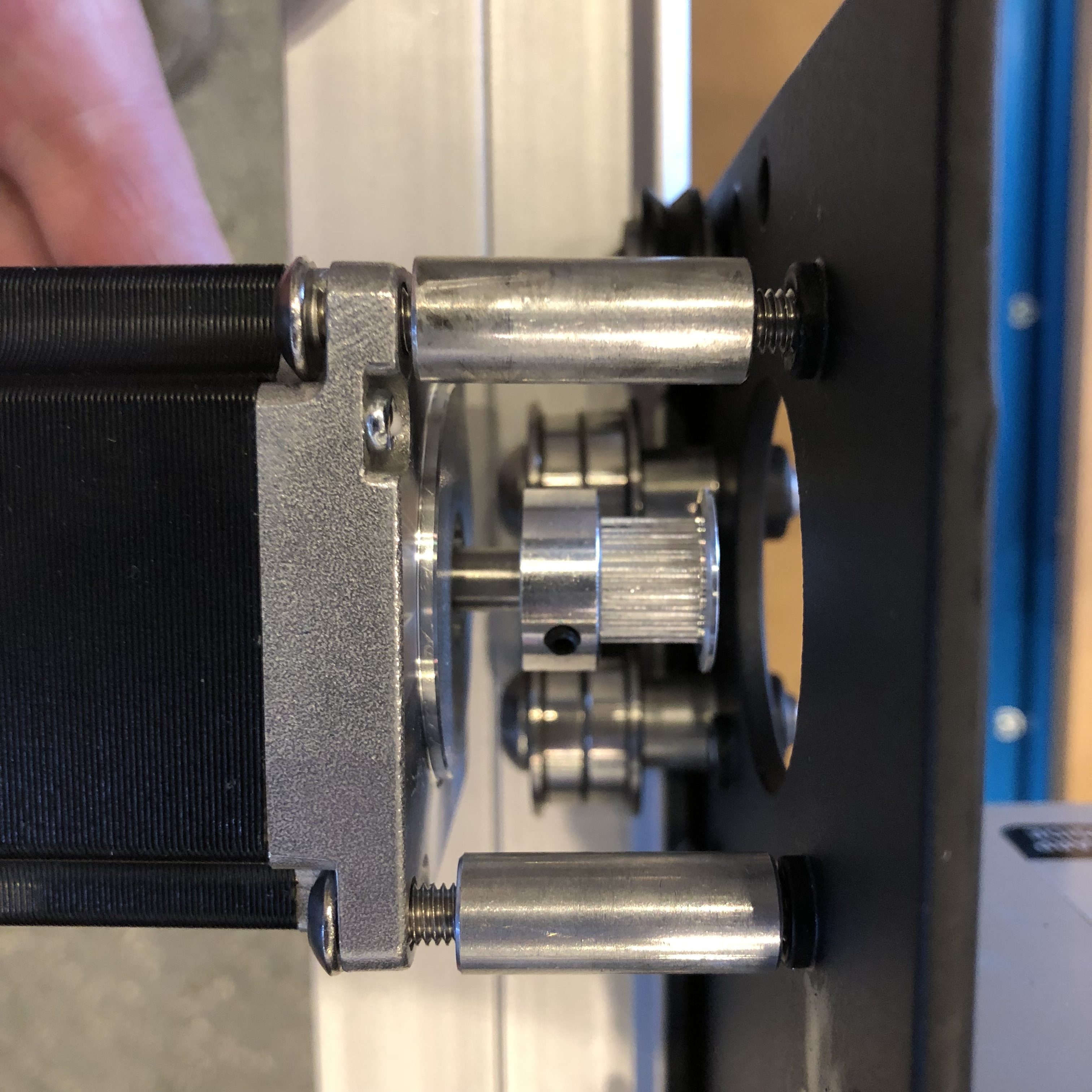
The main issue is the motor doesn’t line up with the pulleys using the new spacers I brought.
It looks like I can move the gear connected to the stepper motor but it won’t budge after I removed the locking bolts…
Thoughts appreciated…
You have to remove the set screws from the pulley on the motor, and remove/reverse the pulley.
There might be two set screws in the pulley, after you remove the one you can see, there may be another in there (the second one locks the first one in place)
The instructions worked a treat. I took photos of each of the steps, including repositioning the cable drag chain. What’s a good place ‘post’ a full set of instructions based on your notes and my photos?
So the final step, it looks like I can increase Y from 360mm to 425mm. The wiki is down so I can’t figure out how to do this so I can take full advantage of the extra space…
Right here works well…
This topic was automatically closed 30 days after the last reply. New replies are no longer allowed.