I took a look at the file and I’ll respond here in case anybody else is interested in what I figured out.
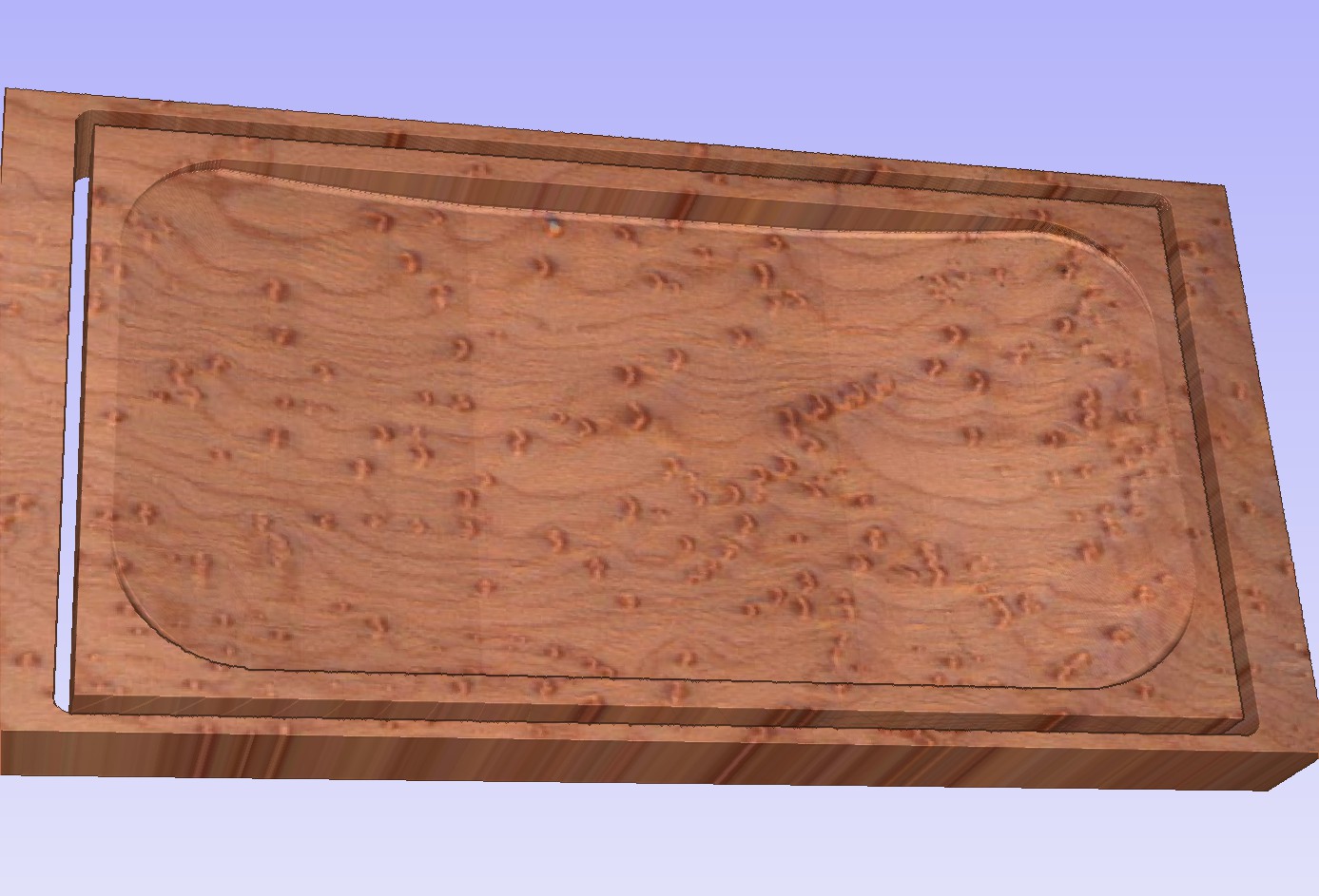
Aspire thinks the model edges are right to the edge of your stock, not to the edge of your piece. This is because of the object called “Limit Planes”. Assuming it’s artifacts of the whole import process?
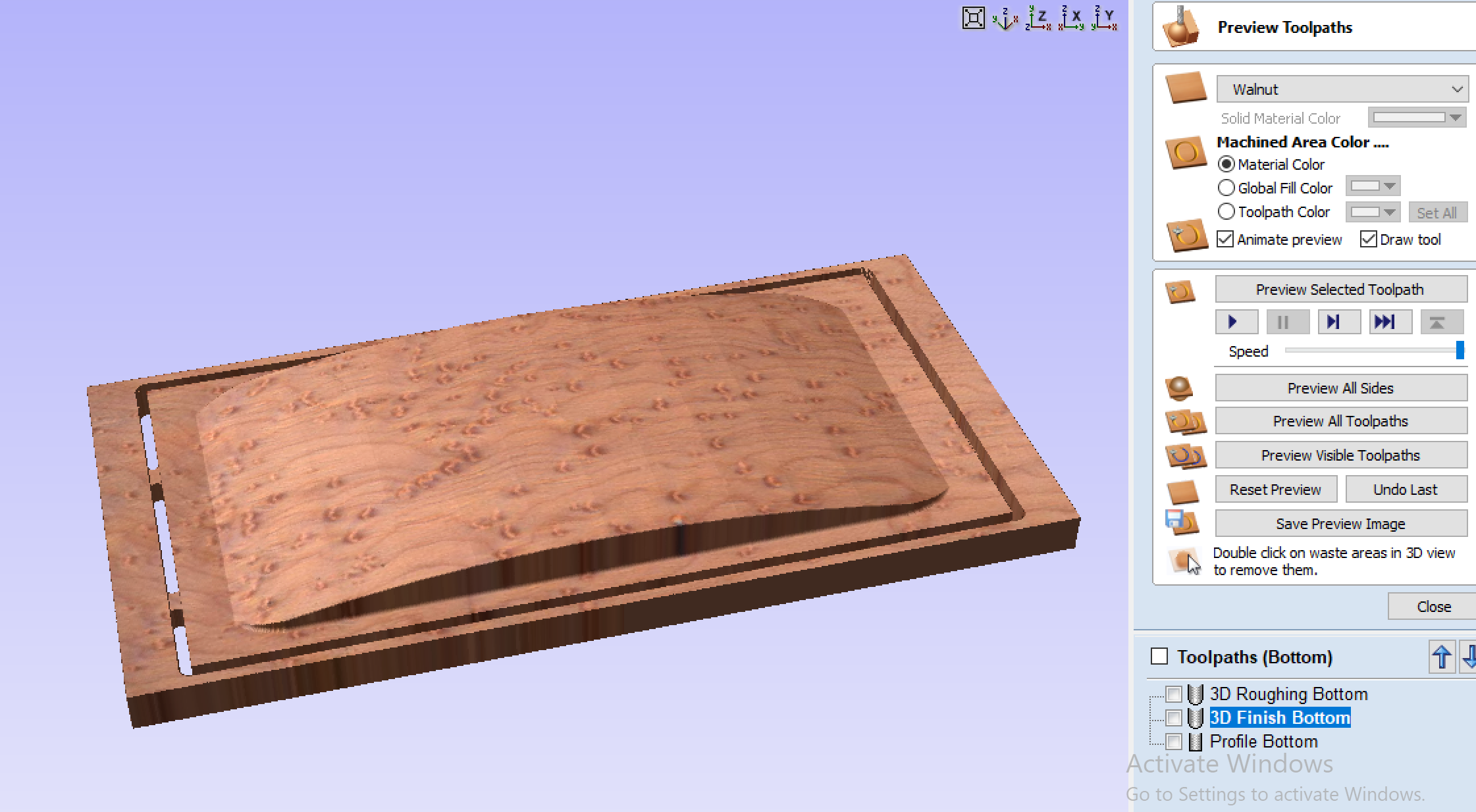
What’s happening is, the 3D passes are covering the whole material instead of just to the edge of your component because there are 3D elements that cover the whole material. Aspire carves ALL 3D elements in the material space, not just the ones you select, which is a pain. Sometimes you want to carve different objects with different toolpaths, especially if they’re far apart, but Aspire just generates a single toothpath for all of the visible ones.
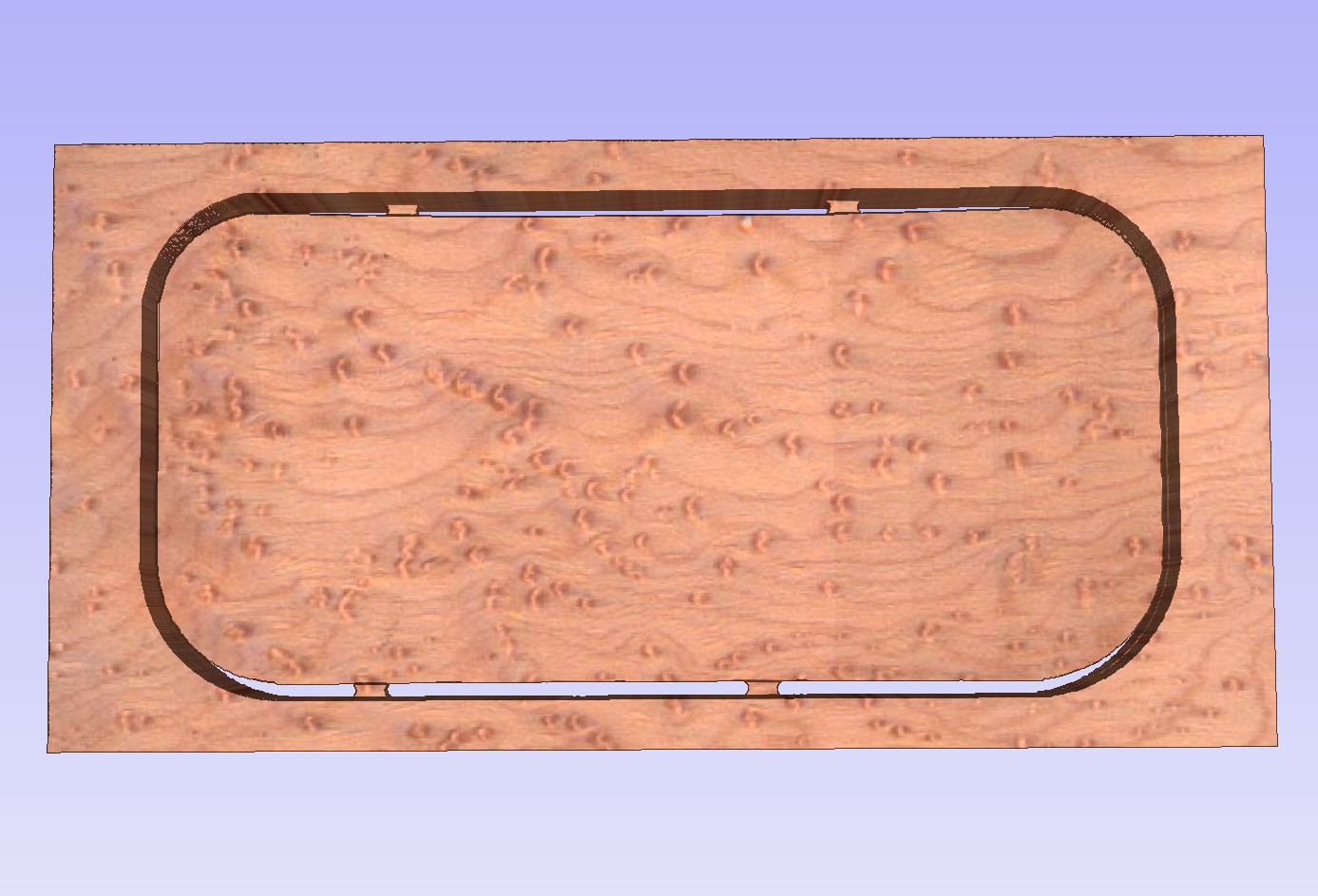
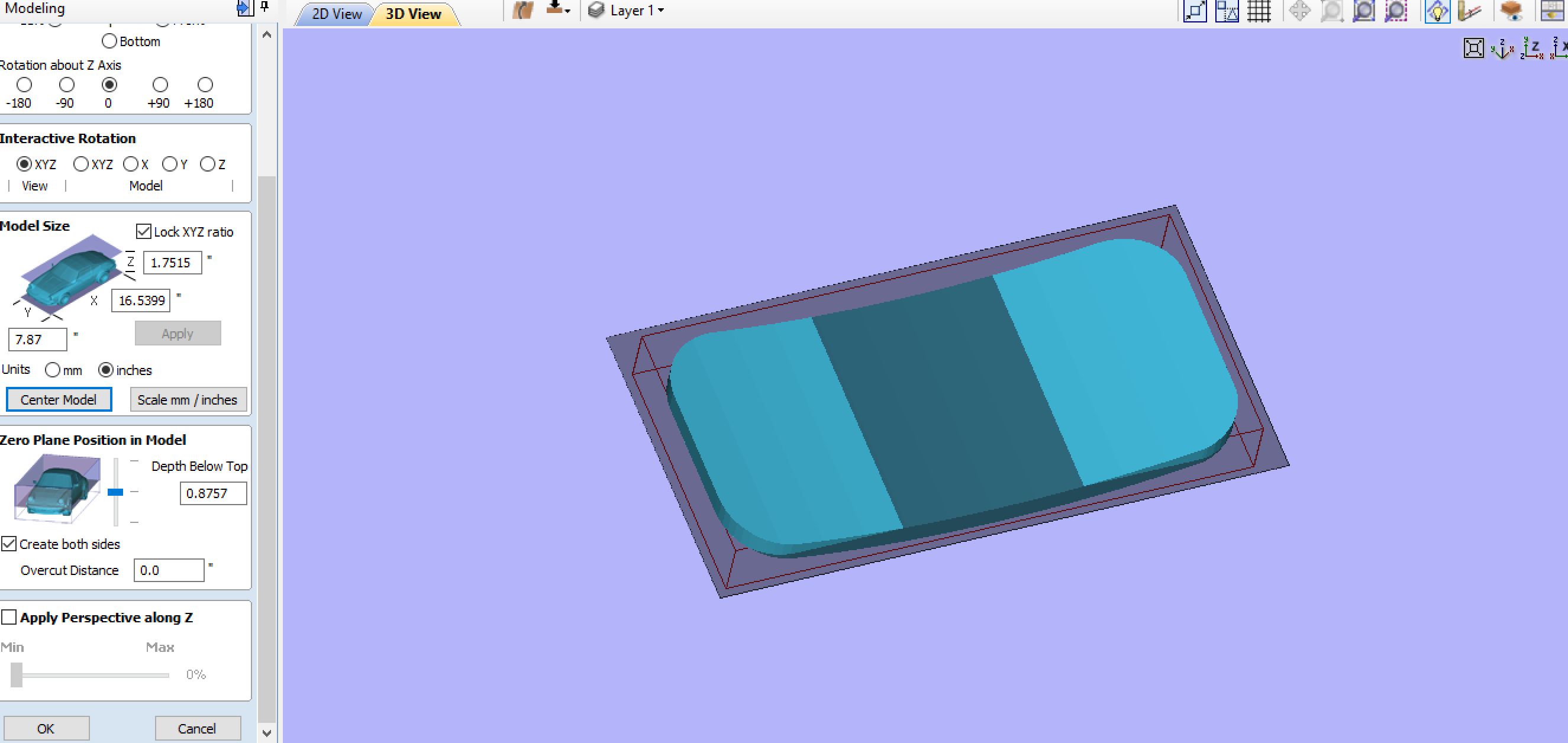
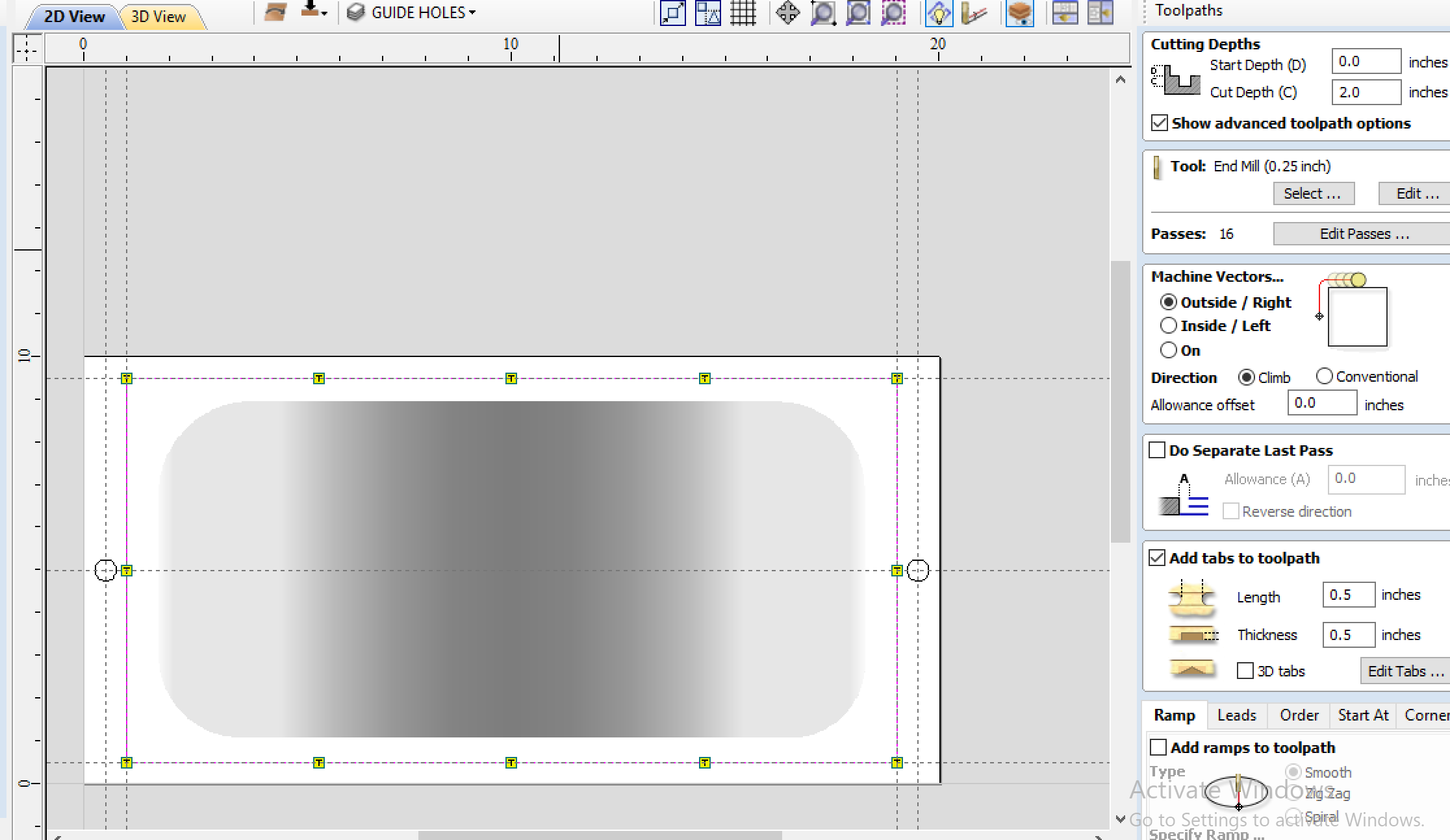
There’s a couple of ways to fix the issue of the extra 3D plane. The simplest is to select, in both the roughing and finishing passes on both side, to only go to the “selected vector”, and select your cutout rectangle. This will only machine up to the line you’re cutting out, leaving your happy little anchoring wood alone. However, what will happen is that the paths will only cut down to the models on both sides but because they’re separate objects, leaving an onion skin left over, like so:
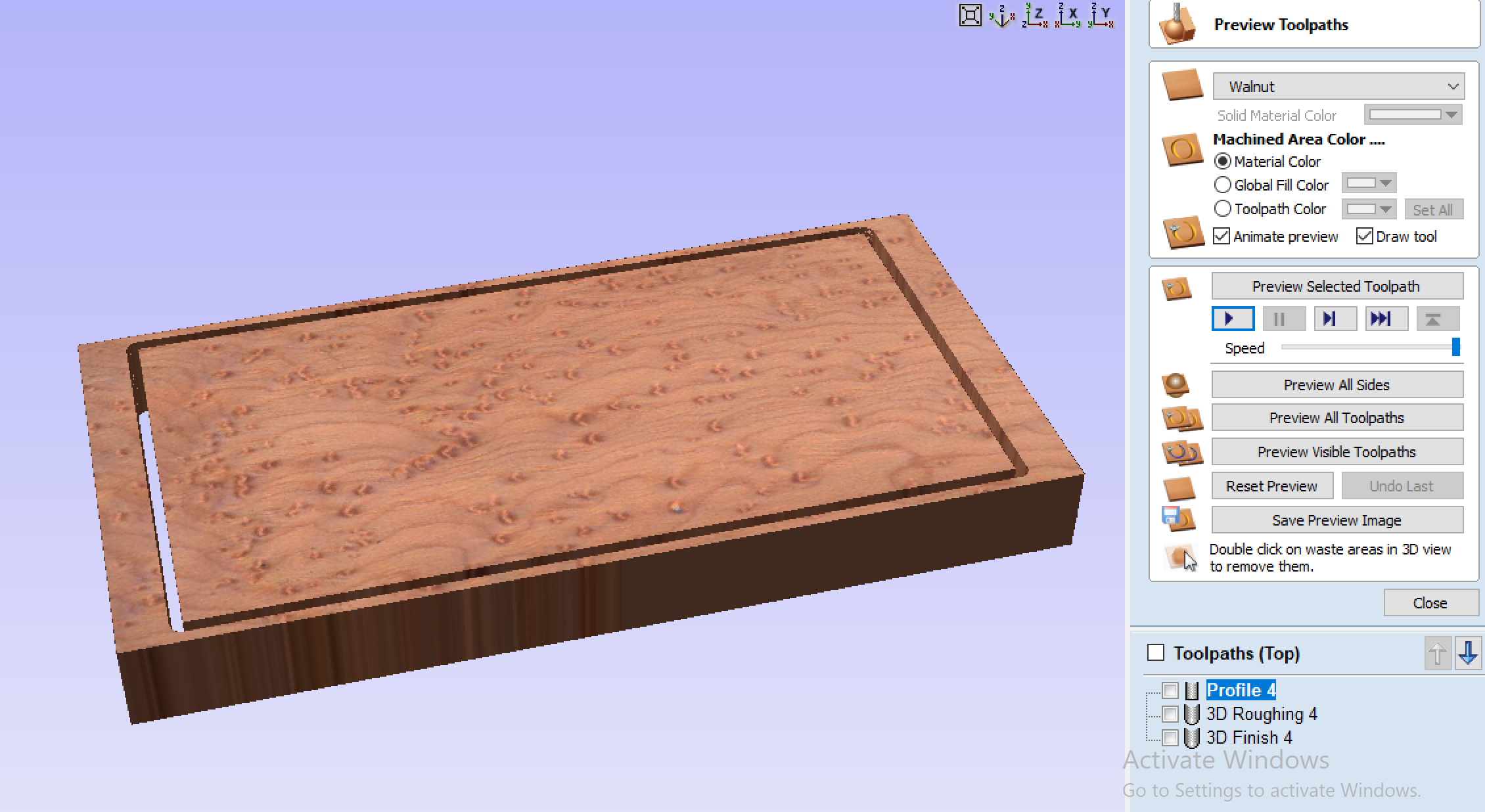
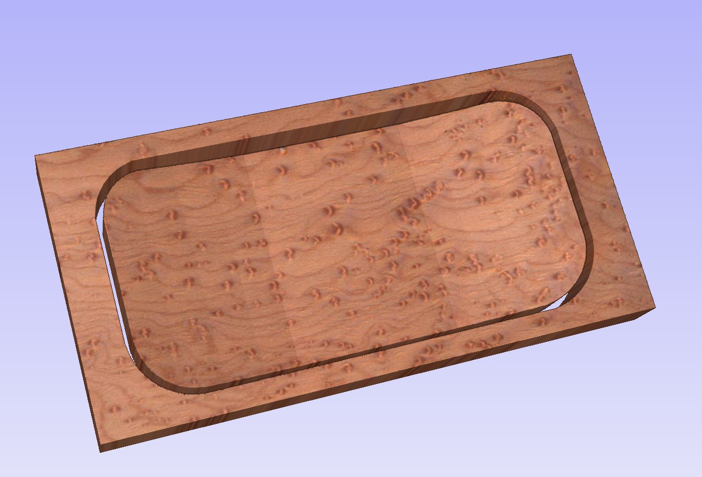
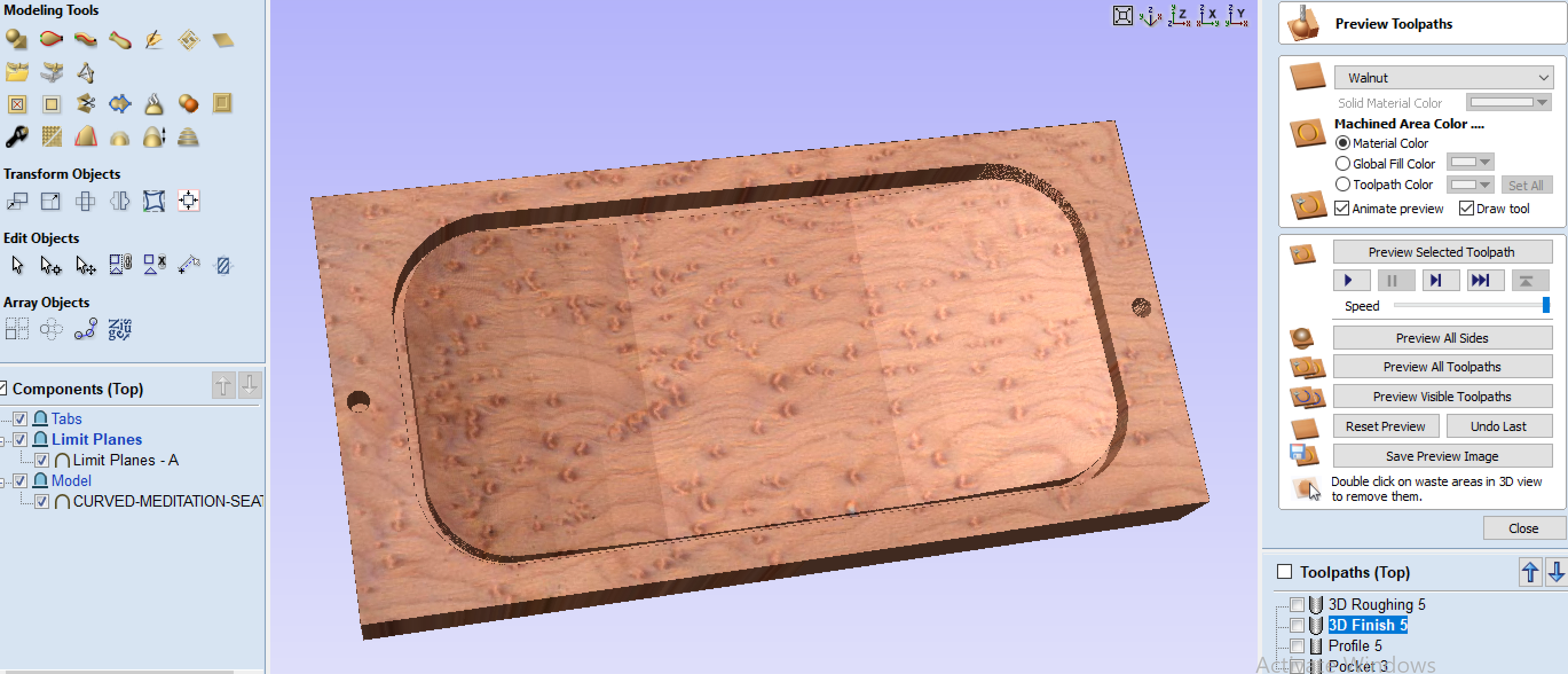
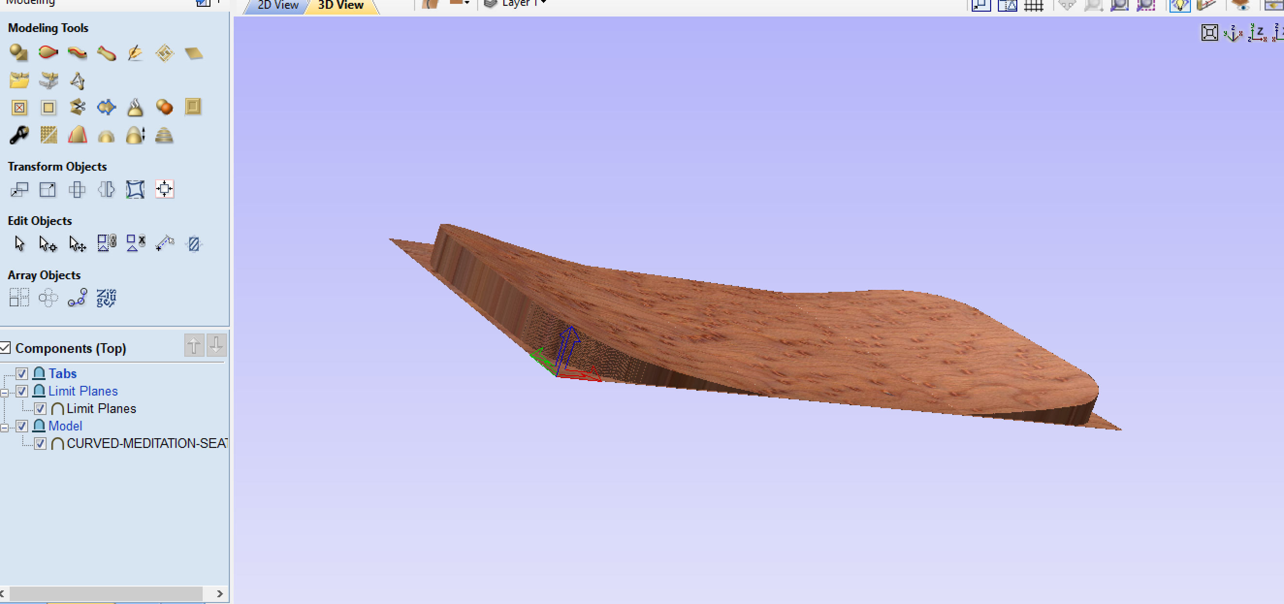
Alternatively, if you choose the object “Curved Meditation Seat” and use the “create vector boundary around selected components” (Middle icon, third row on Modeling tab, blue line around icon) it will create a line surrounding the chair back. Then you can select the “limit planes” object and this boundary line, then use the “split the selected component using a vector” (third icon, third row) and split the object into A and B. One will be the excess stuff to the edge of your material, and the other the bit in the middle of the chair back. Delete the excess and your objects will now be exactly what you need it to be, and you will only carve the seat back. The drawback is that you leave uncarved bits around the curve, like so:
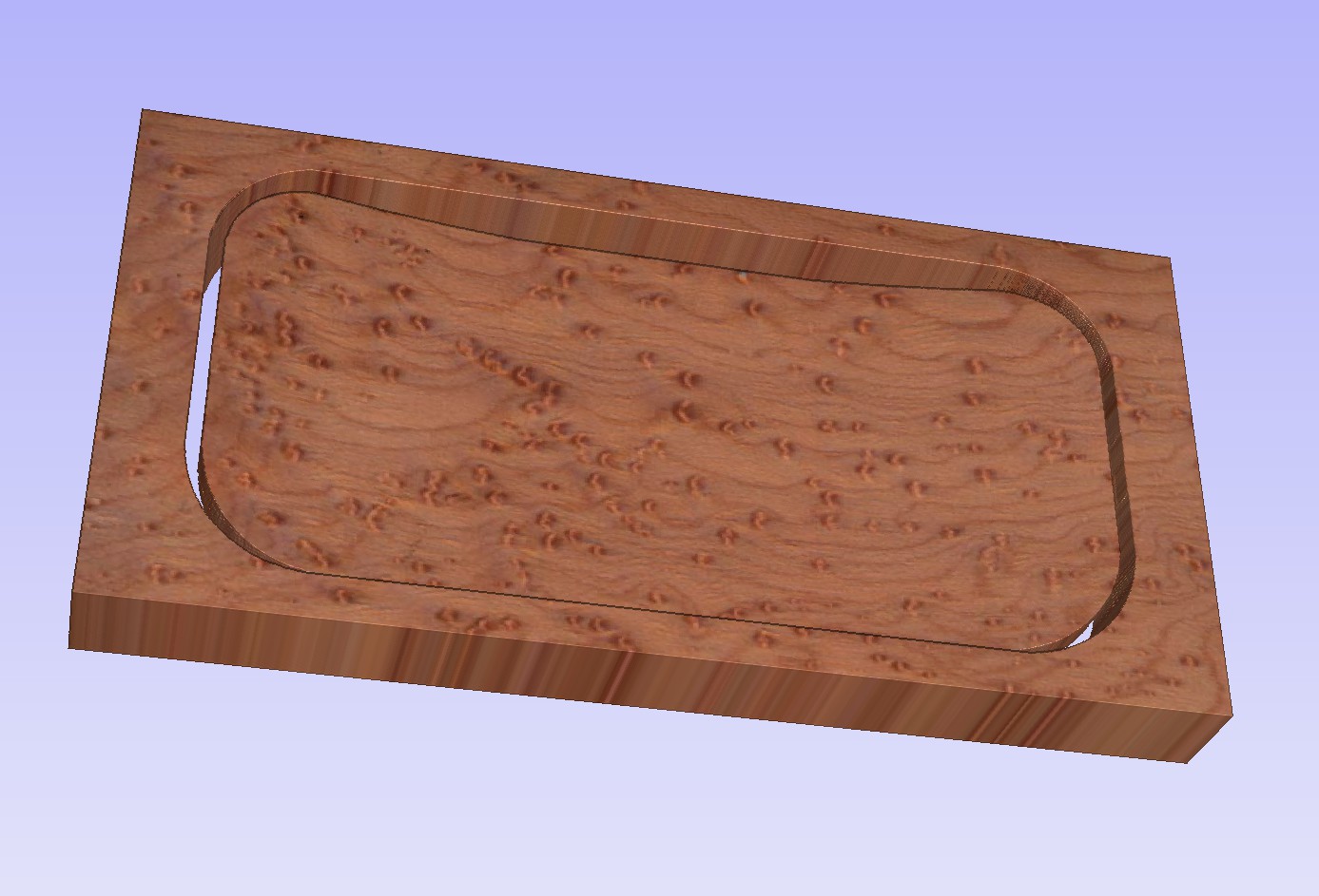
Instead of using your cutout rectangle to do your cutout, choose the boundary line we created above, and you get:
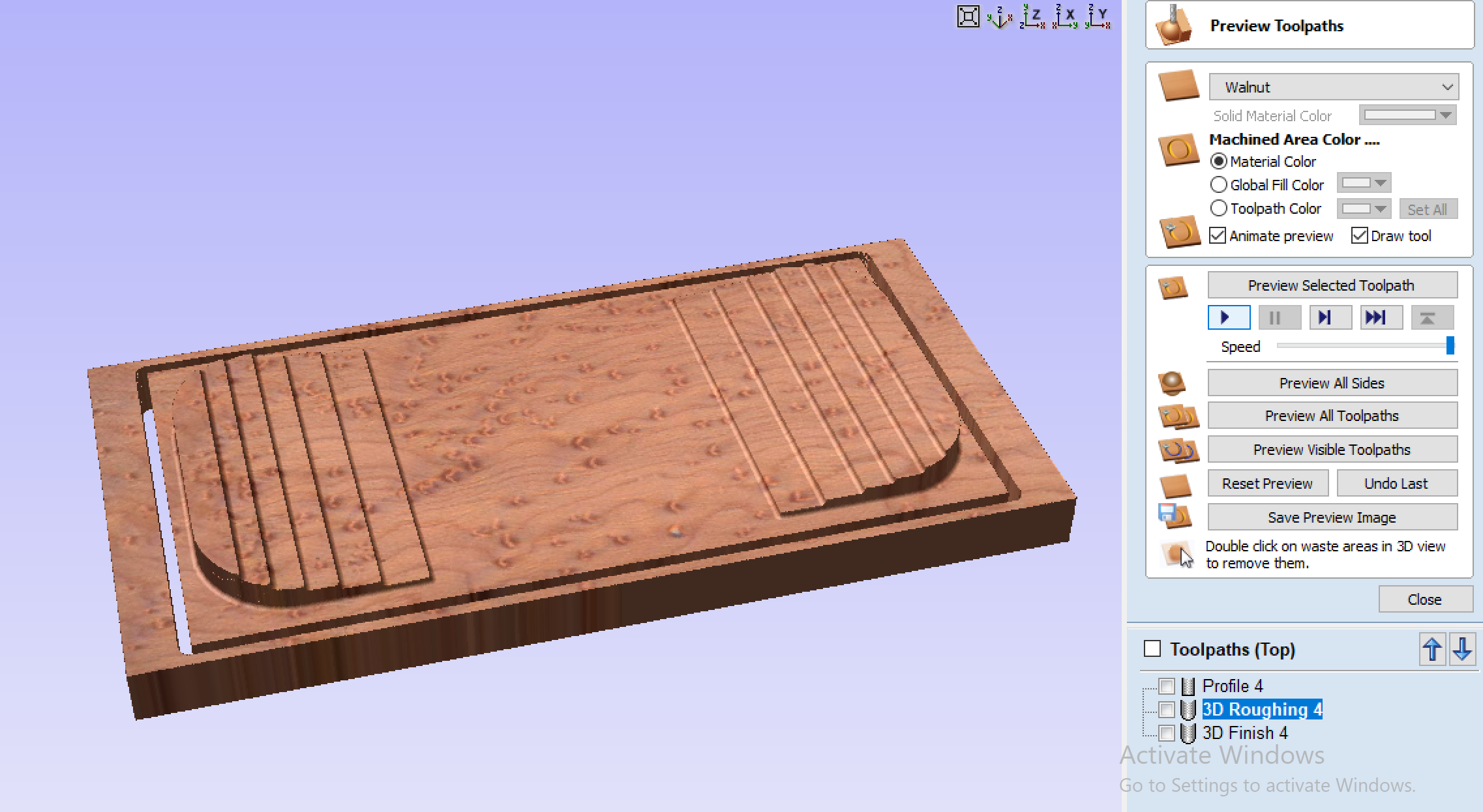
Added bonus of more material to attach to your wasteboard and doesn’t cut in to your alignment holes (not shown)
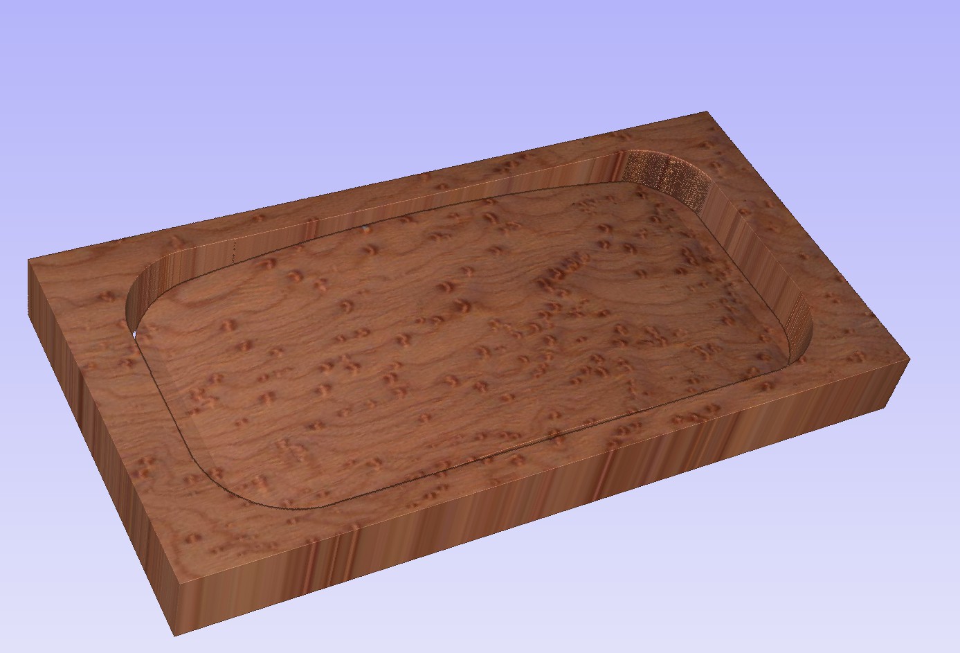
Copy the boundary line to the other side, then cut the limit planes object on the bottom with it. Delete the excess. Regenerate your 3D toolpaths as they are, and change your cutout to the boundary line (you’ll have to generate new tab positions.
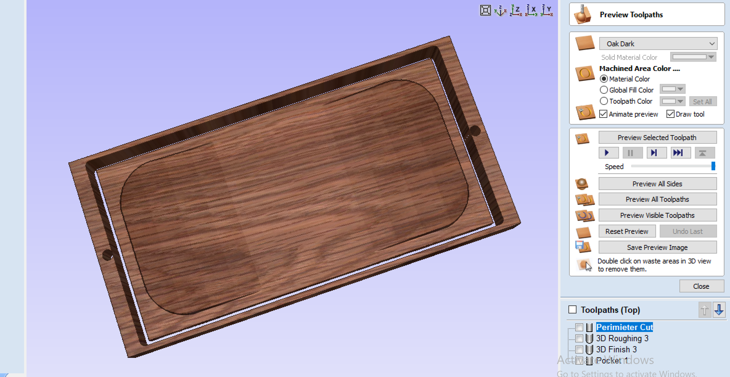
I also figured out why you don’t have tabs. It’s because you have a cutout toolpath on both sides. The bottom does a cutout first, putting tabs at the bottom of the cutout. When you flip it over, the tabs are now at the top surface, and the cutout toolpath just cuts through them.
You only need one cutout though, so maybe just one the second side you plan to do (top?). If, however, you tell the two cutout toolpaths on each side to just cut 1" into the material, then you get tabs half way into the material.
TBH, cutting into 2" material is going to be tough anyway, unless you have a really long endmill (2"+ flutes), and you’re going to have to cut really slow in order to not get a lot of deflection. Might be better to do cutouts from both sides anyway. Do tabs in both, they don’t have to match each other. Tabs on the short sides from the back and tabs on the long side from the front may not even touch the material due to the deep curves.
Some added considerations that occurred to me as I was looking at your file:
For better finish, run a rough cutout toolpath, 0.0625" offset from your boundary line, then a finishing toolpath with no offset. This will limit deflection for a 1" deep cut. If you’re doing 2" deep cuts, you might want to add additional toolpaths to sneak up on the line (one each at offsets of 0.125" , 0.0625", 0.03125" , and 0")
Your alignment holes will be problematic. Cutting 2" through the material and then into the wasteboard enough to put your dowels into will be very difficult unless you have a drill bit in your router. You’re going to need a 1/2" drill bit (your design has 1/2" alignment holes) with a 1/4" shank that’s both long enough to cut 2 1/4" - 2 1/2" deep plus short enough to be able to put it in the router and clear the 2" of material. You’ll need at least 4 1/2" of clearance from the bottom of your router to the wasteboard. If this is an issue, then a solution is to cut a 1" deep pilot hole in your material with a regular endmill, then use a drill with a 1/2" drill bit to finish the job before your remove it from the wasteboard and flip it over.
On the toolpaths tab (right side of the screen) there’s a material setup button. You may want to ensure that the “Model Position in Material” slider is down a little to leave a couple of hundreds gap above material. You can set it up to 1/8" to put it in the middle of your material. This will ensure that any inconsistencies in the material surface will not affect the high points of your model.
Hope this helps, let me know if you need any help or want me to review your design again.

 (editing…).