I just burned up my router because I left it on all night, I forgot I had it running. I have searched but haven’t found a way yet to control the power for the dwp611 through gcode. I don’t need to control speed or anything, just on and off. Has anyone found a way to do it?
None that I have found, and I have been looking. I leave my machine running unattended about 90% of the time, and have to go back into the shop just to shut the router off, if and when the job is completed. A real pain in the @ss.
I have a crazy and simple idea kicking around in my head, that I will probably work on later this fall, but it is only sort of GCode driven. I’ll post some information when I get it up and running,
What I really want , it a simple, cheap, plug and play system, that can be used with any router, any machine, any controller board. Clearly the Super PID is not any of the above.
1 Like
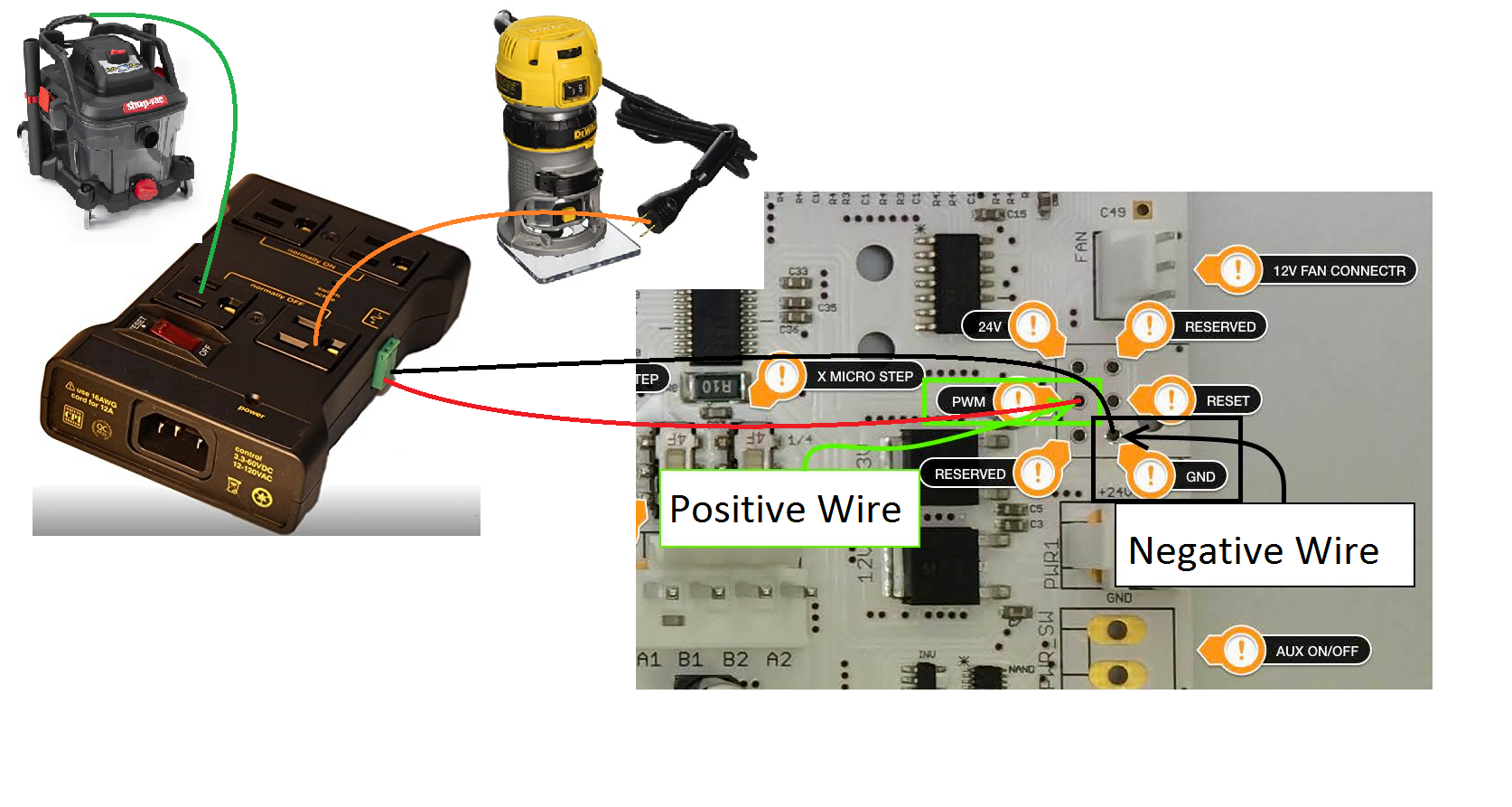
There is no off the shelf solution for this. If you don’t mind a little DIY in electronics, it can be done. The CarbideMotion controller has pins for PWM output. Depending on the version of the CarbideMotion controller, this may be populated with pins or it may not. So far, I have found that the ARDUINO_ISP header is always populated with pins (PWM is pin 15). If you use wires to connect the PWM output and GND (and maybe VCC, depending on the realy package you find) to a 5V relay, then you can use that 5V relay to control an outlet. By plugging your router into that outlet, you will get on/off control of your router. Sparkfun has a tutorial that explains the theory; you don’t have to build the relay board, you can buy one off Amazon.
The PWM signal will give an output voltage between 0 and 5V, depending on the speed you have set for your tool in g-code. If you set the spindle speed to max, the PWM signal will be a solid 5V (I am pretty sure that the max is 10,000 for the default GRBL configuration of the Shapeoko 3). If you have a DMM, you can test this pretty easily. If you set the spindle speed to 10,000, then the g-code should contain a line similar to “M3S10000” to turn on the spindle and “M5” to turn it off.
3 Likes
I’m interested in breaking out the PWM output for practical application, I’ve also looked at the Super PID controller. I’ll also check into the Sparkfun link. Thanks for these informational nuggets.
Wire in a relay:
http://www.shapeoko.com/wiki/index.php/Spindle_Control
Should be able to replace the brushes in the router
I looked at the brushes, and they are still there and look in good condition… But maybe not… I just ordered more, but I think I will pick up a new router on my way home, replace the brushes, and try it. If it works then I will put the new brushes back into the new router and return it. I need it desperately this weekend.
I bought the relay power strip and will try it, hopefully this weekend.
Which power strip did you get? I found this one at Adafruit for $20, but have not actually used it (I have a Super-PID that controls the speed and on/off).
I bought the Iot relay from Amazon, solder wires to the pwm and ground, hooked it up to relay and bam, it works!!
1 Like
Chase,
I’m while I’m waiting for my relay to be delivered, I have a question. With all the problem that the controller card has had with USB disconnects, WHERE did you locate the relay? I was thinking that it might be necessary to place it outside of my enclosure…Talk to me…Any problems (Disconnects, etc?)
Perfect! I am glad it works for you, too.
Will you be adding pictures and links? I’m sure lots of us would like to know more.
I sent Carbide3D an email stating that I had issues with usb disconnects all the time, and can barely get through a cut. They sent me a new v2.3 carbide motion board, and sent me a label to send back the other one. And now I don’t have disconnects anymore. So I would go that route.
1 Like
Chase,
Thanks, I think you misunderstood. I (at present) don’t get any USB Disconnects) and DON’T want any in the future by adding something to the board that wasn’t in their design, which is why I WHERE did you put the relay (Location relative to the controller board). Let’s try this again…
Ohh, I just tested it out last night, I haven’t located it anywhere yet. However, I have an enclosure which the USB runs directly out the back and up on top of the enclosure where I put my laptop. I have the power cord for the carbide motion board, directed to the right of the machine and then running along the base out of the front right. I then have my router cable running out the top front left corner of the enclosure. So I will probably just have it mounted on the front left, away from the other cables, and where my router power cord is already running.
This is about the best I can do right now. But it is pretty simple. And I use RoguePirin’s gcode of “then the g-code should contain a line similar to “M3S10000” to turn on the spindle and “M5” to turn it off.” And those work perfectly. So you would just need to add it in to your gcode.
2 Likes
Most CAM programs have an option to output these for you; just set the RPM value for each cutter to 10,000. When setup this way, you won’t have to edit your g-code to add the lines; they will already be in there.
- Actual setup depends on the program you use.
Yes, this is awesome. Now I just need them to have a homing sequence for tool changes with the shapeoko 3, because I have to set my tool depth at each tool change, and I have the probe sensor hooked up.
Mostly folks just use a separate G-code file for each tool and attendant paths — an all-in-one option would be nice, but would need to be well-coordinated betwixt CAM and communication/control — I believe all the hooks are there, just someone has to make use of them and document the specific steps.
1 Like
You could use the coolant pin to drive a cheap arduino relay and use this to switch a larger relay for the router.
The pwm output MAY give odd readings on a digital voltmeter as it gives “pulses” and as the dvm presents very little load the reading may not be accurate. Also it may give odd behaviour for controlling a relay ( not what it was designed to do).
I have been playing with the pwm output as a pwm is not always the best choice for controlling spindles/Lasers - and have found for reliable results a little electronics added on helps