This will be a tutorial on placing an image and re-drawing it so as to create an inlay suitable for cutting out with a V-bit and 1/8" endmill.
We start with an image:

This will be a tutorial on placing an image and re-drawing it so as to create an inlay suitable for cutting out with a V-bit and 1/8" endmill.
We start with an image:
Once we have an image in mind, we determine the desired size, launch Carbide Create and clear the drawing area, set the stock size (7" Ht. X 5.5"W x 1/4"Thick), Import into Carbide Create using the command Job Setup | Document Background | Edit — select the graphic in the resultant dialog and click OK. Adjust scaling until the image fills the stock area, and adjust transparency as needed.
Click OK | OK | Reset View to arrive at:
We will be drawing this using the curve tool, which uses Bézier curves and straight lines to allow one to define shapes. Originally created to allow for the modeling of French automobiles, Bézier curves allow the drawing of arbitrary shapes with a great deal of control, and without having one change affect another portion of the shape.
Please see http://pomax.github.io/bezierinfo/ for more information.
Each Bézier is composed of 4 points, an on-curve, two off-curve, and an on-curve points. Each off-curve point is associated with an on-curve point — this is represented by a connecting line — and the points should ideally follow some basic rules, both for best rendering, and for simplified drawing and editing:
Thus a circle, when approximated (there is a slight degree of error) as Bézier curves and its on and off-curve points would appear thusly:
We will begin each path with snap to grid turned on, so as to ensure that the path will snap closed, and will place by either clicking or clicking and dragging and releasing either on-curve points which define lines (or places where lines begin/end), the on-curve point, or the pair of off-curve points bracketing the just-placed on-curve point. Place as many points as will be needed to create a given shape, trying to follow the above rules — the grid will necessarily distort the curve placement — for this step, position is not as important as number of points and their type.
Zoom into the path which one wishes to draw, click on the Design tab, click on the freeform Curve tool (fourth from the left), and begin drawing. Click and release will place a point for a straight line (or portion thereof. To get a curve, click, drag and release. The click places the on-curve point, the drag determines that there will be an off-curve point, the release determines where it will be.
After placing all the points and on/off-curve points, you should have something like this:
Note that it may help to decrease the grid size, so as to make it easier to position nodes aligned to other nodes.
Click on the “Snap to Grid” button at the top left of the screen, clearing the surrounding rectangle and turning off that feature, then click to enable “Node edit mode” (the middle Edit Mode button), then drag nodes to their desired positions:
Then switch to the “Curve Edit Mode” (the right-most button):
and adjust off-curve points until everything matches up as desired.
There are three editing modes for curve path objects (from left to right):
Note that curve editing has a number of limitations in the current build of Carbide Create which argue for doing all of this drawing in another tool:
Ideally there would be ways to allow one to:
One would then repeat this operation for each other needed path.
In order to do an inlay, one would of course need a second material to inlay — in this case we will assume 1/8" material, so one would draw in additional inset inlay which would allow one to V-carve the design, use a 1/8" endmill to route out the waste, then use a 90 degree V-bit to follow the geometry and cut out of a piece of 1/8" stock (w/ the stock surface set from the bottom of the stock which would then become the top) which one would then inlay into the piece.
An SVG suited for import into Carbide Create for CAM is at: http://www.shapeoko.com/wiki/images/7/7f/Nobis.svg
Or, one can do a figure-ground reversal:
For each original path, there are two inset/outset paths — select the innermost and outermost and do a V-cut, then pair the middle with its match in the other triple and cut as a pocket.
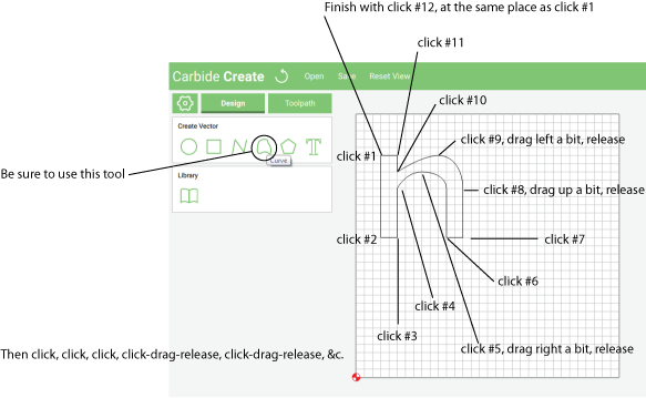
Here’s a step-by-step on how to draw a (rather strange-looking) letter n:
Cc_drawing_n_zoomedin_stepbystep.zip (46.1 KB)
and I missed a click in-between #5 and 6 — I’m going to blame triskaidekaphobia, whoever that is.
and a further discovery:
===Node editing commands===
In addition to being able to drag nodes around, when a path is selected and “Node Edit Mode” is engaged, one may right click on the path to insert a node, or right-click on a node to delete it.
Okay, let’s try this again.
New image:

which we place onto a 2 inch wide by 1.25 inch tall work area thusly:

Except, we’re going to draw on it, then merge images, then re-upload the image — hang on, working through that now.
So, instead, place this on the background:

Download the original from: http://www.shapeoko.com/wiki/index.php/File:Cc_n_pathpoints.png
using these settings:

Then use the curve tool to practice re-creating and editing the drawing — click on the on-curve points (with snap to grid turned on), click and drag to the off-curve points, releasing at the faint grey highlight.