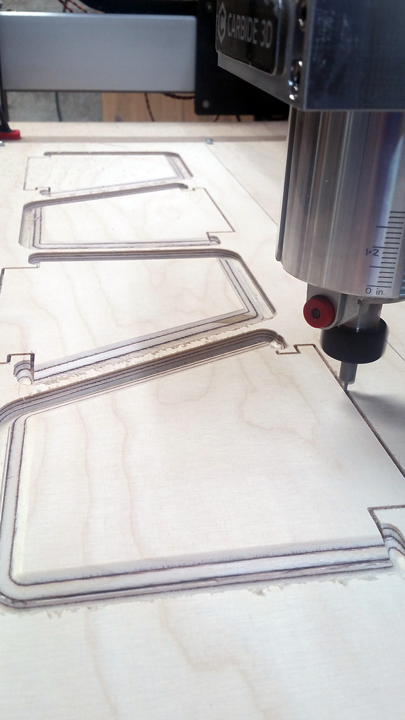
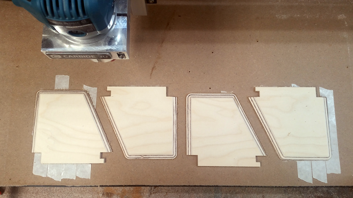
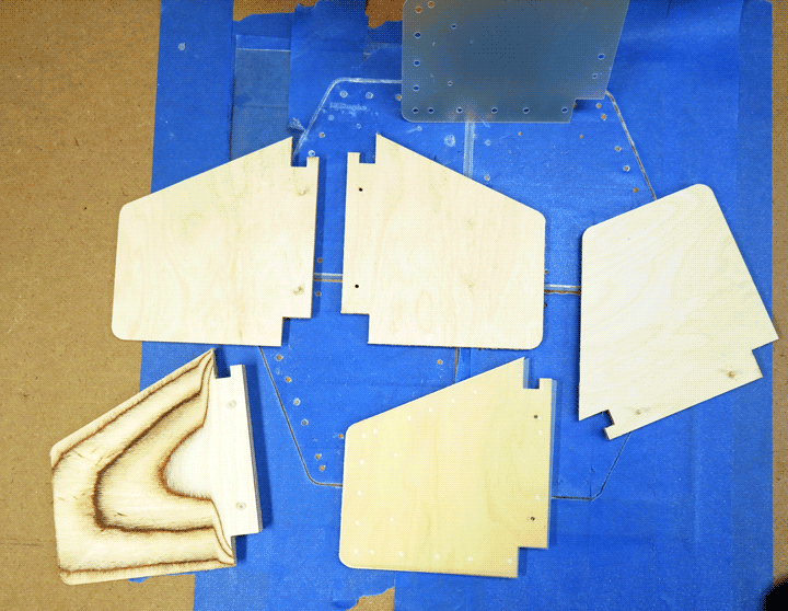
Fins for a 4X upscale of the Estes WAC Corporal Model. The fins are about 11 cm by 11 cm. The finished rocket will be about 110 cm tall.
Cut from 5 mm light aircraft plywood. Roughed the bevels with with a 3mm ball-end, finished with a 6 mm ball end. Cut the fin tabs (the parts that will go inside the body tube) and separated it from the stock with a 1.5 mm two flute straight router bit.
The Fusion 360 simulation made it look like I’d need to sand off some tool marks, but the bevels are smooth and ready for primer right off the waste board.
What is the original BT size used in your kit @jvl? I manufacture HPR avionics and I too built a custom 4" scale WAC Corporal (sustainer) many years back (with custom nose and tail cone).
Hi Jim. The original Estes K11 kit used BT20 (18 mm ID) tube. I am using 65 mm heavy wall paper airframe tube – so 3.6X (4X to 1 significant digit). For sentimental reasons I am building it to look like an upscale of the 1970s model rocket, not a downscale of the 1940s JPL sounding rocket – so no tail cone. I may not even fill the wood grain on the nose cone or the fins.
I am keeping it as simple as I can. Single deployment. No avionics. I am overbuilding it, since I plan to use if for my L1 certification attempt some time this summer. Simulations look good with motors from a G54 to H250. At the top end, Open Rocket claims it’ll break 1000 meters on an I200.
Rob, I am not sure it would solve my issue. I’m using Nitto DS tape. I am getting good adhesion, and I don’t have a problem getting the work pieces off the waste board. I want something I can cut into that I won’t have to pick out of the flutes of the end mill. Something friendly to plywood.
Looking forward to seeing your other Shapeoko parts (centering rings, bulkheads, etc) and finished bird. Good luck on your cert flight. My L1 was also motor eject, and back in the day it flew with a Vulcan “Smoky Sam” H115 if I remember.
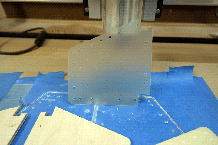
Since you asked, here are the centering rings (finally):
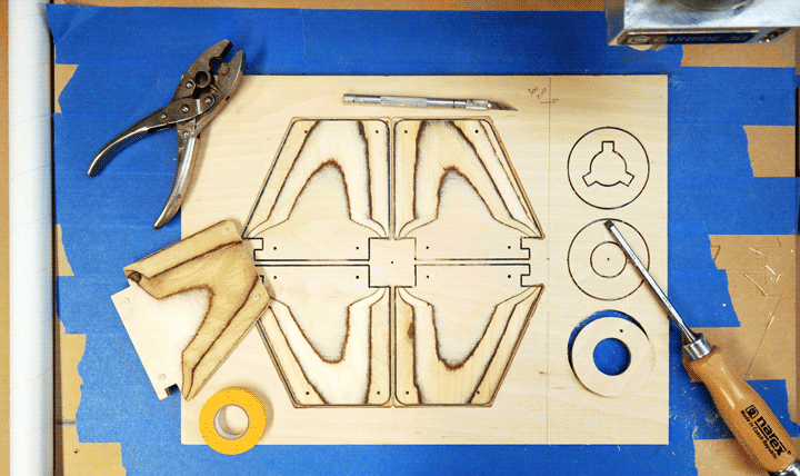
This is after redesign. We couldn’t make it to the high power launch in June, so I decided to use the delay to try cutting airfoil fins (instead of just beveling them on three sides). LOTS of learning in Fusion 360 (the loft tool, the sketch-intersect tool, sketch mirroring, construction planes, construction lines, etc) and not a little trial and error on the Shapeoko.
Worried about the strength of the fin, in case the rocket comes down on a fin tip, I planned to put a fiberglass (0.5mm G10 sheet) between the fin halves. After a couple of messy failures with F-clamps, and piston clamps, it appears that clamping the curved the fins halves for a long epoxy cure will require a fixture cut to match the fin profile. As much as I want to figure out how to do that, I want to launch in 2 weeks – so I am just going to adhere the fin halves with Titebond and toughened CA, soak everything in wood hardener, paint it with thinned CA, and put in a bigger parachute.
Cutting the fiberglass dulled an expensive 1/16" endmill really fast.
To back up the glue with a mechanical support I am pinning the fin tips and root with nylon screws. I’ll cut them flush after the glue hardens.
F360 is very cool, very powerful, but it is a time sink. I ran AutoCAD a million years ago, and I have experience with Maya and Lightwave and Blender…and some tool in F360 is always just enough like a tool in one or another of those things to trick me into believing that the learning curve will be short and shallow, Invariably the implementation is different enough from the similarly named tools in all of those things that I hear myself yelling at the computer a lot.
I spend way too much time playing with designs in F360, and not nearly enough time cutting. And it is the cutting that is killing me on wasted time and materials.
The first iteration of the centering rings, I used F360’s “trace tool”, which ran the bit around the outside of the outer circumference and around the inside of the inner circumference. The offset is half the cutter diameter, so the rings were 1/16" too wide to fit in the body tube and 1/16" too narrow to accept the motor mount tube. I could have filed them down, I should have filed them down, but instead I burned a couple hours playing around trying to figure out the failure mode.
I made the same error when cutting the Garolite inserts. I cut four pieces at once, but I didn’t think to check the direction the tool was running. Two of the pieces were perfect, two were undersized by 1/16" in every dimension. This was especially frustrating, since the fiberglass is so nasty to cut.
I am sure that this detail is covered in some tutorial, some FAQ, some reply to some users’ forum… but I didn’t even think to look until the parts came off the board and did not fit.