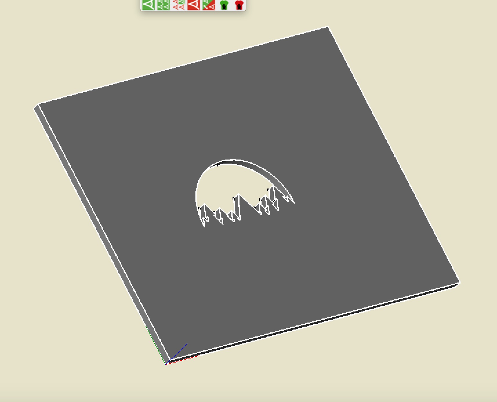
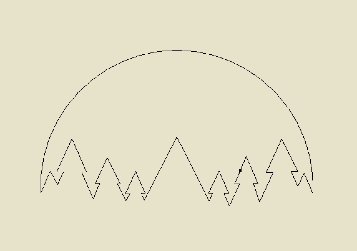
I am having a couple of issues inserting my DXF into Carbide. I have a file with trees on it and each set of trees will be a different depth. So I have approached it as I need each different set to be it’s own DXF. I tried importing my DXF that was exported from Creo but all I get are the curved lines. I then opened the DXF in Inkscape (successfully) and tried to import the SVG into Carbide but either get very thick dual lines or I still only get the curved lines and no straight segments.
For SVG, one needs for everything to be combined into the minimum number of paths possible, and where possible, closed. There should be no overlapping, and if possible, no intersections.
It seems to extrude in a 3D cad app I use, which is a good sign.
With Adobe Illustrator the file imports as text on a page.
You might want to check for point objects, and then erase them.
Okay, opening that in Inkscape gives us 47 discrete objects — we only want 2 for an SVG.
This ought to work:
Select the inner set of paths w/ a drag-select and do Path | Combine to get an object w/ 86 nodes.
Drag-select to get everything, then shift-click on the just combined object then repeat Path | Combine to get a path w/ 8 nodes.
Arguably we can combine everything into a single compound path using Path | Combine.
but it doesn’t for some reason (at least not w/ Build 300 which is what I have installed at the moment here)
Exporting to PDF, doing exactly the same things as well as correcting direction and removing overlap and then re-importing as a PDF into Inkscape and re-saving as an SVG results in a file which does work.
I appreciate the help so far. Unfortunatley I have not solved it yet. I followed the tips for Inkscape and managed to get it to 2 discrete objects but when I then try to import into Carbide Create, I still only get the top arc and no straight lines. Do you have any other options? I attached the new file that still is not working but is 2 objects.
As I noted, to make a file which worked I had to dump to PDF and fix it using Freehand.
Opening your file in Inkscape, then resaving as a .pdf, then opening that in FreeHand results in a composite path, which it ought not be, and when that is broken apart, 40 some objects — stitching them together in FH works of course, but that’s not something which other folks can depend on.
In Inkscape applying Path | Stroke to path and then deleting one of the copies works — some corners become rounded, but they could be adjusted by hand if need be, and would be unnoticeable if the stroke weight was adjusted. Probably punching the object out of another would work — I’d suggest filing it as a bug report.
So I appreciate the help so far, it helped me get the file in the system and create a part. However, after cutting I realized the file had a “thickness” to each edge and basically left a non-cut border around each area. I think the file came into Inkscape as shapes instead of as a path. Is there anyway to change from shapes to a path easily?