Hi Mark,
It sounds to me like you are over driving the motor. Likely it’s moving too fast for the weight subsequently causing it jam.
Change $122=100
$112=500
Hi Mark,
It sounds to me like you are over driving the motor. Likely it’s moving too fast for the weight subsequently causing it jam.
Change $122=100
$112=500
Hi Luke / Mrbeaver, Thanks for replying so promptly… That’s what I thought and did. Same result…
The part that has me puzzled is the z axis does the juddering thing randomly even when I remove the spindle and move it by hand. In this scenario, there’s no extra weight - there’s no spindle at all! Have carbide 3D made a machine that fundamentally doesn’t work? I don’t really understand the physics, but I imagine it is down to small variations in loads between the 4 v-wheels and 2 rails? Is there a way of making the travel reliably smooth? If so, the problem goes away. Loosing steps only happens when the z-axis goes into it’s juddering mode. I have been pretty meticulous with cleaning the rails and v-wheels. I have taken it all apart and they wheels are all turning smoothly and the rails are parallel. If I added more wheels would that smooth the motion out?
Probably I just need to switch the z axis out for a ball screw linear actuator, like the one you sell?
I don’t know enough about steppers. by turning the speed way down like you suggest, does that improve it’s torque, or is it just allowing the physical geometry of the rig react slowly to whatever dynamic physics is going on? Does slowing the steps down reduce the torque? I asked carbide 3d to give me the full specs of the motor so I could compare it to others and research it’s properties, but they have been not very helpful. They told me my brand new inoperable machine was unsupported because I put a spindle on it. (ignoring the part about the problem persists even without a spindle attached). Pretty unhappy with them.
So much for after sales support. Probably should have gone with a more robust Chinese cnc for similar money. I would have got no support from them either, but that would not be a surprise…
Sorry for venting…
Any further insights into steppers and torque delivery would be most welcome.
Personally I’d find that C3d offer some of the best support I’ve ever come across. I’m surprised they won’t support it on a new machine.
From the above it wounds like you might have a bad stepper of faulty driver. If an axis isn’t moving with no weight then something else is wrong. Does the motor work when off the machine i.e. no load?
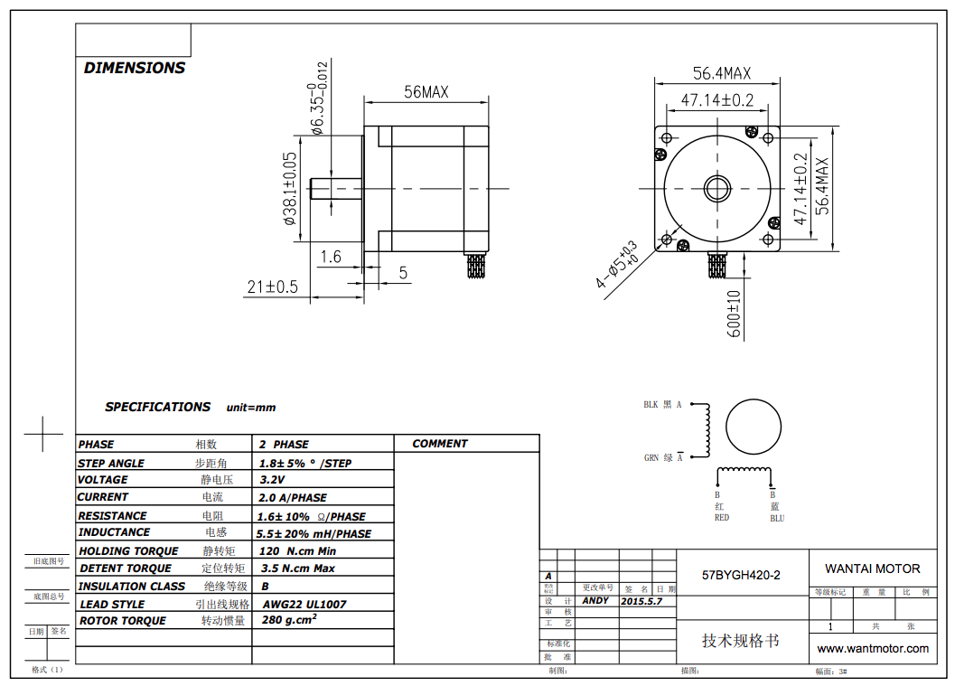
As noted on the wiki, https://wiki.shapeoko.com/index.php/Parts#Motors the motor specs are:
The Shapeoko 3 uses NEMA 23 stepper motors, 125 oz.in, 200 steps/rev
If you’ll let us know the results of your difficulties when the spindle is removed, we’ll gladly do our best to work with you to ensure that the machine works to its specifications and your satisfaction.
I’ve been chasing stepper problems myself lately. “Singing”, stopping. Mine all traced to the Molex connectors.
First was the connector for the X axis extension that came with my XL conversion kit. It was buried in the middle of the X drag chain. I discovered it to be almost untouchably hot. Cut it out and spliced the wires.
The most recent was in X as well. Traced to the male Molex on the C3D board, corroded some how causing intermittent faults.
Of course, consider that my machine is some 3 years old now. Not new like yours.
Anyway, check the Molex. Easy enough to do.
Thanks for these great thoughts. I’ve been busy at work and have not had much chance to mess about. Hopefull can move things on tomorrow… I’ve just tried again using the very slow z settings you suggested Mr Luke/Beaver. The job worked to a point just past it’s personal best. i.e. a little further than it went before before failure when I tried it last time…
So I thought to my self if slow is better what about REALLY slow? I used $112=50 $122=25 (!) I knocked it out of the park - it went much further than before, and then… failed…
The job took so long that my laptop went to it’s lock screen. I don’t know when exactly that happened, but when I tried to click the pause button, due to audibly missed steps, it didn’t work because my laptop was on the lockscreen. So I’ve learnt that I have to change my lockscreen timeout on the machine I use to drive the Shapeoko.
I continue to have dynamic physics problems with the Z axis.
I reiterate to WillAdams who I guess must be carbide support? I have the rough travel happening randomly without the spindle attached - I mean physically removed from the shapeoko (zero weight) - and me moving the z axis manually up and down. It’s fine, nice and smooth one moment, and the next juddery and unsmooth. ++ungood! When it does the rough motion thing it takes much more force to make the Z carriage move. I theorise this is the state the Z carriage is in when the missed steps occur. I think the missed steps are a manifestation of the rough travel mode because it happens randomly. Just as it does when moving the Z carriage manually…
I don’t know what is causing the rough travel mode. I’d like to know. If I could eliminate it, I think there’s a good chance the machine would work even with my heretical spindle.
BTW Carbide, spindles are amazing. Enormous power, small form factors, unbelievably quiet, cheap. I have a lot of experience with a 2hp Hitachi TR-12 hand router. I would be very happy never to turn that noisy difficult tool on ever again. The thought of using a trim router of the same design in the Shapeoko seems bonkers to me. Things must be different in the USA I guess? (So glad I don’t live in New York any more…) I wonder why you don’t embrace spindles as the way forward for Shapeoko’s? It seems illogical to me.
OK enough ranting… I need to increase torque in the Z stepper or stop the out of the box #roughtravelmode of the Z axis.
Can I:
What do you think? is the fix 1, 2, or 3? is there a 4, etc.?
Looking at the prices I should try buying the stepper motor. If it works, great, If not on to the ballscrew?
Will that motor work with the CarbideMotion v 2.4e board?
I’m a little troubled that Carbide3D sent me a machine where the Z carriage v-wheels were over tightened to a point where they did not rotate properly, and the Z axis rails were not parallel by more than a mm top to bottom over that tiny length… Makes me wonder if my problems are all just setup? Is there something else they could have done wrong at the factory that could be contributing to this trouble? I have read many times about how the machine works well. for others…
I hope I can get to the bottom of it soon.
M
Hi Mark
Looking at the above, I believe you either have a faulty Z carriage/motor, wiring or controller. Something in that mix is not working as it should.
Whilst I offer the HDZ as an upgrade path for most users it’s not a mandatory upgrade but only one I’d recommend for heavy duty users. The stock axis works well for most (I used one for almost 2 years) and pushed it hard.
I don’t work for Carbide 3d, however I think if you can demonstrate to them the fault over video with no spindle attached they will support you and get you running. Carbide 3d offer the best support I’ve ever had and have always done right by me.
I would not pursue any of the three options above without getting a definitive solution with the stock kit at this stage as there is clearly a underlying issue.
Luke
What Luke said.
And, to reiterate, a short video is worth a thousand words. Carbide support is peerless, they will get you up and running as soon as they understand the problem.
As for aftermarket spindles, it is my OPINION, as a multi year SO3 owner/operator, they are overkill and unneeded by 95% of SO3 users.
Having said that, to each his own.
I enjoy modding tools I use in my shop if I run into a work requirement that can be improved by a mod. I do not attempt any mods until I’ve learned the operating parameters of the stock tool.
Good luck, we’re here to help.
Thank you both for taking the time to reply. It’s great to know there are people out there who have huge experience and are willing to help if they can. I really appreciate it. Hopefully I can pay your kindness forward.
Good point about videos and photos…
It’s early days for me and the 3rd job for my shapeoko after the wasteboard and clamps is the ‘table’ to mount it onto. At the moment it’s on the concrete floor of my laundry.
Here’s a video of the smooth and rough motion. It’s audible as the deeper knocking sounds - not the plink stretch sounds of the springs… Sometimes it’s smooth sometimes it’s not… I rechecked tension was good on the v-wheels and the Z tracks are parallel. All the leads look good to the Z stepper. Nothing gets over-hot. The timing pulley on the stepper is very tightly attached. No slip. 2 grubscrews on the stepper timing pulley are well engaged. The Z timing belt is tight (but not too tight). I tested again, and the X & Y do the juddering thing too. Makes me think this is just something that happens with 4 v-wheels engaged with V tracks? Maybe I need some lube? Candle wax or graphite or something? I don’t want to put anything on that will attract dust… The whole system is pretty good at doing that already…
Should I try swapping Z and X steppers to see if the X fails after I do? If the X failed while using the originally Z motor, that would isolate the problem as being the stepper?
Following the link from WillAdams I found this which is the spec for the supplied motors I think?
I note you have 2 sets of springs on there. What happens with one set?
The clunk/grr sounds like the motor engaging - as these are turned it generates a voltage - thats what it sounds like is happening.
Can you show a video of the motor driving it.
I’d not recommend putting anything on the V wheels or tracks.
Ok, more clear now. To add to Luke’s comments. The juddering in un-powered movement is completely normal. Move the gantry the same, it will judder too (I see on re reading you noted this). Steppers are acting as generators, if you have a Carbide3D probe you will see the LED light up.
If you could video an air cut for us that would be helpful. Pick/make a file with max movement in Z. Set your Z close to the wasteboard and run the file. Something like this but with more Z movement:
You can run a psu up to 35 volts and get more torque and not damage the control board. Obviously, the one you have is 26V, and they’re a little hard to find with a specific voltage and the right connector. Its easier to find one and swap the connectors.
I’ve refit for high torque steppers on my machine, but they require higher voltage to generate more torque, when I did that I also replaced essentially the entire carbide control board mechanism. I have an article in the forum on the whole process. I’m very happy with it. I will say that most of the grbl boards out there are junk - anything less than $20 or so is a knock off of a really nice design with crappy parts, and no support for current grbl. You want this one: ($20) Arduino CNC Shield – 100% GRBL Compatable | Protoneer.co.nz with a real arduino uno r3. The carbide board is actually very good, it’s foibles are minor.
Thanks again everyone for continuing to reply.
Now that you mention it I had read somewhere about the steppers generating power when you move them manually - actually it makes perfect sense that they should! Of course they will use the power to try and hold the step… I double checked by removing the belt from the z axis stepper and moving the Z carriage manually… smooooooth…
This is why it’s so great to have people who have been around the block with this stuff. It’s opaque until you gain clarity through insight & experience. My apologies to carbide for my ramblings due to a misinformed mental model of what was going on.
OK, so now I don’t have any rational explanation for why my Z axis sometimes works and sometimes does not. In a typical fusion360 3D adaptive clearing toolpath there is a lot of lifting and repositioning. My Shapeoko with it’s admittedly heavy spindle perhaps works 100 times, and then on the 101st fails to lift the Z-axis you can hear the thunk-thunk of it missing steps. (and another job is ruined)
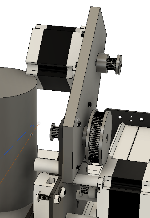
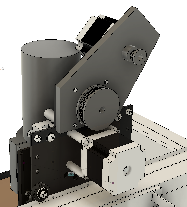
I have a stepper with more torque but the same amperage etc on order. Hopefully if I swap the stock Z-stepper for a higher torque one, the problem goes away? The next phase if that doesn’t work is mechanical advantage. I’m thinking something along the following lines might be the simplest? Minimal backlash and 3:1 advantage for small $$ I might even make it in plywood to start with to prove the point and then make it properly in aluminium as phase two?
It’s kicked to the side so as to miss the spindle and it’s water cooling tubes etc. (in my pictures I need to move the stepper out a little further out to miss the spindle.
This would be connected with a GT2 9mm belt like the stock Z.
I actually have 3 sets of springs. I tried using just the stock springs. The spindle drops when the power goes off, but that’s not necessarily a problem. I added more springs to see if neutralising the weight of the spindle would help. It does help a bit I think. But I’m still getting missed steps. I think it’s about the right amount of spring because when the power is off, I can position the spindle at any Z height and it does not move up or down. It’s neutral. An industrial designer friend suggested I could use a counterweight perhaps? He envisaged a weight equal to that of the Z carriage including the spindle hanging from a cable going over a pulley and attached to the Z carriage. Although this would neutralise the Z carriage weight it would also double the weight and increase inertia for the X and Y movements, I don’t think I’ll be trying this one!
This video shows cutting going well, and then, failed steps on a -Z move. I’ve tried slowing everything down to a snails pace. I also tried just slowing the Z movements. To be clear, when this happens, the belt is not slipping on the timing pulley. It’s the motor missing steps.
Cool! Google video links appear to drop right in to whatever this forum software is 
My decision to buy a water cooled spindle was mostly about not annoying the neighbours with the noise. Secondary was a water cooled spindle is a closed system. No dusty air being forced through the motor. Aesthetically that just makes sense. I have a plan, again mostly for the neighbours benefit to put the machine into an enclosure to minimise the noise. Enclosing a brushed trim router in a very dusty environment seems to me like a fire waiting to happen, or failing that an unhappy medium to run an air cooled motor in. With that said, I also have a plan for a dust extractor, so the dust problem goes away, but the noise problem gets worse!
I’ll do that video of powered Z movement up and down when I get a chance.
Thanks again everyone for helping me out. I’d be lost without you!
Update: I finally received both the high torque stepper and the pulley. I bought the stepper first, then looked again at it’s specs to find it has an 8mm shaft. The one from carbide is 6.35mm. No problem I thought to myself. I’ll just buy an 8mm pulley. I looked quite hard, and couldn’t buy one in Sydney Australia or from an Australian shipper at any price! So I ordered from China… but that means waiting 10-15 days unless you shell crazy money for courier delivery.
I soldered the new stepper to the pins of the carbide-supplied Z cable (I didn’t have the connecter, will rectify that soon…) It seems to work. Before I screwed it into the machine I tried to stop it turning while it was running on the bench. I couldn’t. It is seriously higher torque than the carbide motor. And this is running at lower amperage than the motor can handle. The carbide control board outputs 2.5A whereas the motor is rated for 3A. Someone told me that you can hook a higher amperage motor to a lower amperage driver, but you get an almost linear loss of torque…
The 8mm shaft meant that I had to buy a 20 tooth pulley instead of the 16 tooth one supplied by carbide. Again, slight loss of torque due to it’s slightly larger diameter - longer lever arm.
I have high hopes that this is all I’ll have to do to make my setup work reliably. While I was shipping pulleys from China I bought the belt and larger pulley so I can do the mechanical advantage thing I explained above if I have to. (but I’d prefer not to!)
This is what I bought:
It works!
That’s a monster stepper!
Don’t forget to re-calibrate your Z steps/mm before you plunge your bit through your waste board. 
I know! Right?
Yep, I forgot to mention the Z recalibration. Thanks for the reminder.
There is one more thing I didn’t mention. I found a recipe that made the machine with the stock stepper work…
I was talking it over with my wife (who tolerates my interest in CNC with some grace). She said “have you tried swapping out the computer you are driving the machine with?”. Err, no… So I did. It worked! OMG something about my old laptop I guess? After kicking myself for not doing this earlier, I got to work on the routing job that had been on hold. I got my mouse from my old laptop and setup the new job on the new computer. Then, OMG it failed. Wait a minute, it worked reliably before (I did a 3d toolpath with loads of z-axis moves for about 45 mins.) The only thing that had changed was the new toolpath and the mouse… I unplugged my USB mouse and tried again. The job worked!!
I’d be interested to know if anyone else has had issues with other USB devices messing up their shapeoko? I’ve not read anything to that effect, but it’s pretty obscure. Probably I fell asleep before I read that thread! Also I never would have guessed a USB mouse might interfere.
I’ve not actually had a moment to try driving the shapeoko from the old laptop without the mouse. (and i’ve gone and messed up my control experiment by swapping the stepper in the meantime)
Ah well. Onwards!
So after some serious frustration and the Shapeoko stopping randomly mid job, Carbide support said I was getting electro-magnetic interference or a ground loop problem. After looking up what those meant, I got a multimeter out and discovered nothing is earthed on the shapeoko. The control board is supposed to be I believe, but I could not see it when I tested. Fortunately I had added a Z-probe, one side of which is grounded. So I ended up making a holder from aluminium hanging off a grounded copper water pipe near my shapeoko. Now that my touch plate is stored in a grounded state, (still attached to the ground pin on the touchplate connection on the board, the machine works perfectly even with the old mouse that gave me gyp earlier… So weird you have to discover and jump through these hoops to make the thing work…
I grounded everything together on a marine grade grounding bar. 120v, 240v, VFD, spindle, frame, and control board. Run spindle power through my drag chain without shielding. No issues, and don’t need a ground clip for my probe.
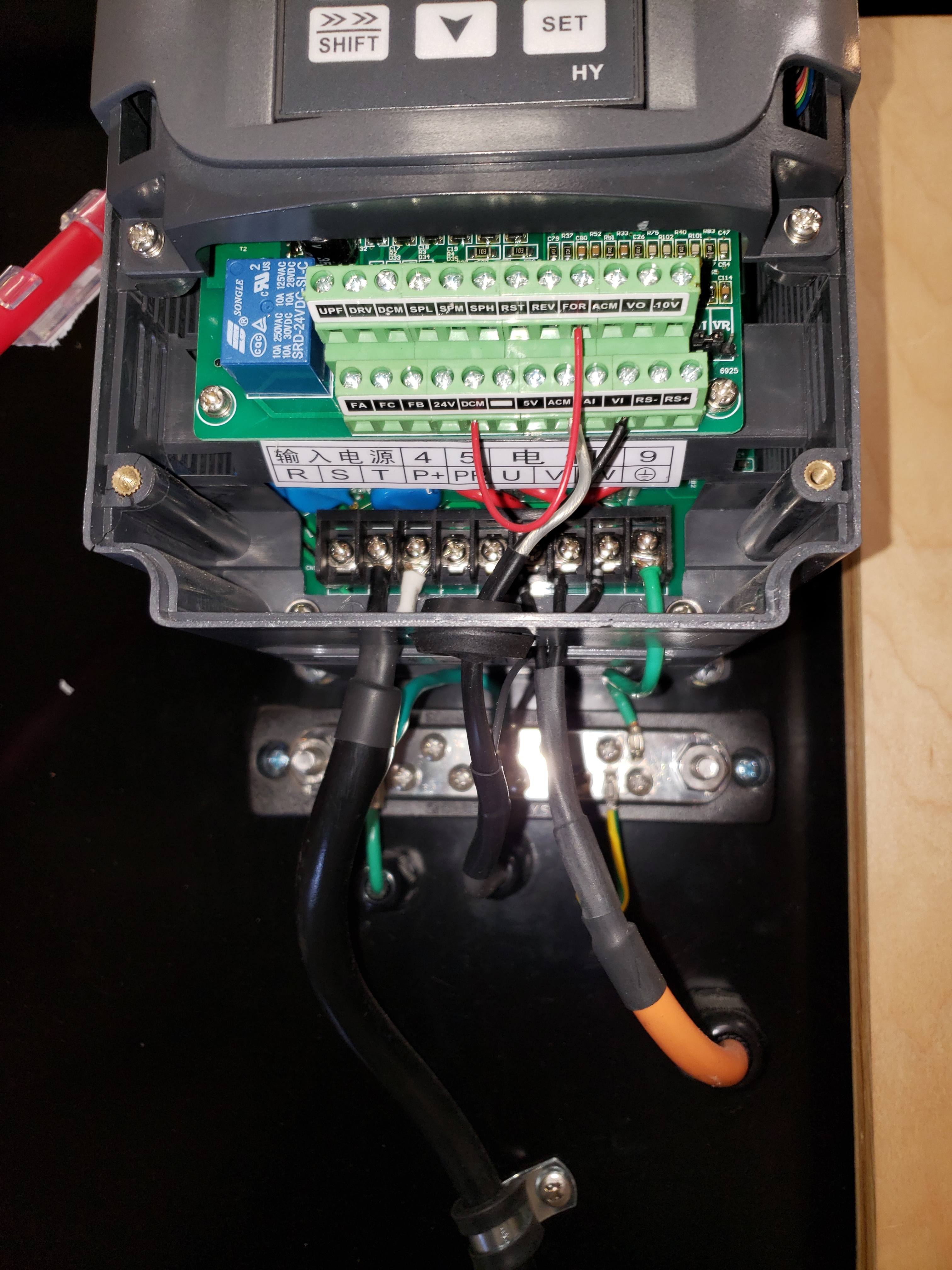
Just installed the spindle and VFD and cannot get it to work.
If I go step by step using steveandrews settings the spindle starts up when I enter the value of 1 for PD001. I have to hit the stop button to make it stop and it never runs again. Ignores everything from the Shapeoke board and entering the value of 1 again does nothing.
Are there any updates on how to get this working? I am pretty sure I have it wired correctly since the same PWM signal starts my power supply relay just fine
Miglo mentioned needing a jumper J1 over V1. Could someone clarify this? Does he mean a jumper between them?
Thanks…