See below for anyone who wants to take a look at the full assembly of @Luke Z-Axis with some personal mods.
CAUTION - If you do decide to download and import this to Fusion 360, make sure to create a new folder and import into that. I make extensive use of sub-assemblies and parts folders. The Fusion 360 import brings these all into a single folder so it’s a bit of a mess. Also, if you want to delete you have to do it in the right order respecting dependencies. It’s a dose to do.
Other things to note
This is based extensively on Luke’s design but there are enough small deviations that the parts are unlikely to be interchangeable.
I’ve only copied over the work on the base plate needed to make the Z-Axis, I haven’t included Luke’s additional design work to allow this to be used for any other axis.
Unlike Luke’s original design, this is vapourware. I’m waiting for my ball screw before starting so this only exists as a design. Subsequent issues could arise when I go to build it.
This won’t work with the ball screw Luke gave dimensions for above, The required ball screw is included as one of the models.
Any feedback welcome. Happy to answer any questions on the Fusion 360 drawings.
Hi Luke, I’m wondering about the Z height (depth) problem that you guys discuss in Carbide3D where their program doesn’t allow some kind of depth that is now available with your Z axis screw upgrade. My question is whether you have tried Estlcam in conjunction with your ball screw z axis to get full depth of the new ball screw z axis? I use Estlcam exclusively and have never had any problems as are so prevalent on the forum. I’m not promoting Estlcam, just wondering if it would answer that depth problem that is causing some to sway from C3D code generator. Any thoughts?? Jude
Morning Jude. Yep within Carbide motion there is a soft limit that is applied to the software ontop of the machine soft limit. Because my Z has something like 20cm of real movement I had no choice but to change controller. My Z is also much narrower which also meant I gained more X travel.
I can’t say I tried Estlcam, but I did have to make the move to UGCS. I have had a learning curve but no issues that were not my own doing. I’m tempted to try Estlcam but over than advanced probing I’m not sure what benefits it would give me over UGCS.
Griff
(Well crap, my hypometric precursor device is blown…)
44
Thanks for posting the Fusion files. I’m looking forward to your continued posts as your build progresses.
Nice! A full motion model! This inspires me to continue my climb up the F360 learning curve.
Any idea how the weight, sans spindle and mount, will compare with the original Z? I would guess less which would help to mitigate the additional weight of the larger spindle and mount.
Also, will there be an “easy” way to tram the spindle?
Finally, should be simple enough to mod the spindle plate to accommodate the standard DeWalt or Makita routers for those of us not quite ready to do the full spindle upgrade?
Sorry, one more - a link to your ball screw supplier, please?
The biggest advantage of Estlcam for me is the way it brings in files from sketchup, svg’s and such, if there are any breaks it is so easy and quick to fix the breaks without having to resort to “other” programs. I only draw in sketchup and have had zero issues with any drawing going into Estlcam. I don’t want to learn more programs or get bogged down writing scrips or code so I just draw in sketchup and estlcam cam the cut files and send it to the Shapeoko3 with Estlcam with absolutely zero errors, except mine personnal errors. That;s what so great about the Shapeoko 3, it obeys absolutely even when I am wrong, never argues or complains. The other main thing I like about Estlcam is that it is written from a user’s point of view, nomenclature is common sense like, no mystery language, it’s has explanations included for every command “just hover the mouse” and it discribes the command. I know nothing about UGCS and kinda leary of my learning curve when I have something that works for me on it’s own. I don’t want to suggest you try Estlcam just so I can find out if it works with the new z axis upgrade because I will eventually follow your lead with it, but maybe I did hint at that…Anyway, there you go and I appreciate your threads here especially the ball screw z axis upgrade. Thanks Luke, Jude
I think @TommyG who did the model has inspired a few of us. I must say I’ve been learning about all kinds of fun things in fusion since he posted the model. I’ve challenged myself to watch one video a week on how to use it. The worst part is after watching a simple video on sketches I found I’ve been doing so much stragely for so long
I would think the whole assembly would be heavier, but then again I’m running a spindle that is twice the weight of a dewalt.
The tramming is really easy, see this post: Dialling in my machine using the 'Aluminium block method' - it took me all of 30 min. I would like to introduce another method but front mounted screws would be best - but thats not for this machine. This is V1. V2 is being explored… anyone mention square rails?
You could easily adapt this for the dewalt router. Just 2 holes in the facing plate not 4.
The ball screw supplier is in the first post
@grumpa - some really good points. I must say I found UGCS very confusing to begin with, but I think I’m there with it now. I likely could go back to Carbide motion if they allowed me to use custom machine settings. I’d love to have the advanced probing from Estlcam but it means learning more software when I just got to grips with another and from a design element I’m 99% fusion. I like the precision and some of it’s functions. I might take another look at Estlcam at some point though.
Luke (@Luke ), you may consider a look at bCNC just for kicks. I tested it at the same time as UGS, and I’m fairly certain that I like bCNC better. It seems more intuitive to me with more features, but that is of course a subjective opinion.
Griff
(Well crap, my hypometric precursor device is blown…)
48
Luke, sorry but, how do I specify the spec for the ballscrew to the vendor you point to at Ali Express?
So Tommy has made a number of tweaks and improvements to my design.
Mine is tried and tested but his is more refined - I have no doubt that his is better - I’d follow his spec.
Griff
(Well crap, my hypometric precursor device is blown…)
52
Luke, actually I’m not committed to either design. Just trying to ensure I understand all the nuances involved in ordering the parts.
I shall wait to see how TommyG’s design actually comes together and performs. I suspect you will both be making tweaks/refinements to your designs. If I’m patient I’ll benefit from all your hard work .
@Griff, just an FYI, what I’ve been doing. Instead of AliExpress, I’ve been searching through Amazon. I’ve found some sources for the same parts (probably from the same company as well) but they include the machining and bearings / blocks without having to specify. I may go this route, so that all I have to do is design my own plate to hold everything. Here is an example:
The coupler is the only thing I am concerned with here, as you need the correct size to work properly. NEMA 23 motors have a .25" (6.35mm) shaft diameter. But if you go with something like Tommy’s (@TommyG) design, you won’t need the coupler, just the right belt pulleys and drive belt. From what I can tell, I think this is a “safer” design in that it doesn’t put mechanical stress directly into the motor, but I don’t know how easy it is to lose steps this way from the belt slipping, which is what we are all trying to avoid with a ball screw in the first place.
1 Like
Griff
(Well crap, my hypometric precursor device is blown…)
54
Evan, this is most helpful, thank you!
Not being a mechanical engineer means I really have to rely on others when considering upgrades such as this. I’d prefer to do it right the first time, so I’ll continue to monitor others progress!
Whilst in theory you can use off the shelf components for this, that one won’t work - its too long. Both my design and Tommys use custom length ball screws. You could still do it, but you will need to re-design the back plate.
If you use a support kit like the BK/BF you will also need to custom design the rail support - then you are making your own kit.
Belt drive in theory is safer, because you can slip a belt as you mention there is the chance of skipping. I doubt you would have an issue driving a ball screw directly - I don’t unless I try to jog at 4000rpm.
No problem. I’m not Mech E but I did stay at a Holiday Inn Express last night…One thing that the above link doesn’t take into account is the linear rails on either side that would be needed to keep things steady. So there is that part not accounted for. I don’t know about purchasing from this site, but here is a nice place with explanations of what BF/BK 10 means and the bearings involved. http://www.controlresourcesinc.com/bs_end_supports.htm
This is a VERY rough estimate because I haven’t entered individual materials for most of the fixtures and fittings but Fusion is listing the new design as weighing 6.4kg (that includes the two stepper motors) and the original Z-Axis assembly as weighing 6.9kg (again including two steppers).
It’ll be an interesting experiment to actually weigh it to see how it compares.
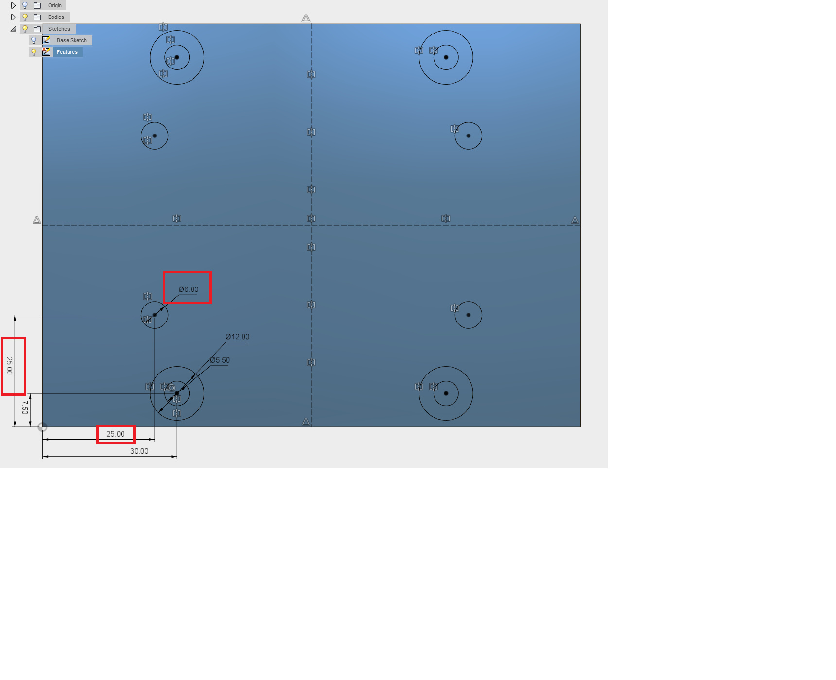
Yep, design is easily modifiable to suit your own mount. If you look through the files for one called “Spindle Plate” and then edit the sketch called “Features” you can change the spacing of the spindle mount holes by changing the constraints on the bottom left mounting hole. I’ve setup the sketch to use symmetry around the X and Y axes so this will modify all four holes. This is shown in the image below.
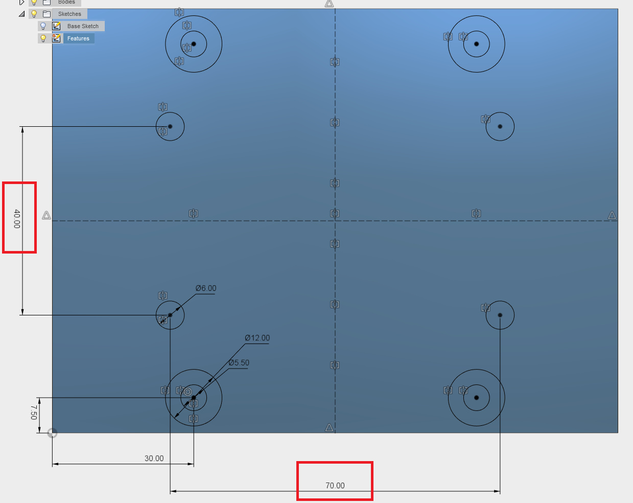
The way I constrained these wasn’t the easiest for making this change though. What I’d recommend is deleting the two linear dimension constraints highlighted above and putting in two new constraints between the bottom two mounting holes and the left two as shown below. Then you just need to enter the values for the spacing of your mounting holes and symmetry will automagically do the needful.
I’ve recorded a screencast of the process, it should be at Screencast Title in a few minutes. At the end of the screencast I update one of the sub-assemblies but it doesn’t update with the new layout because I forgot to save the original part.
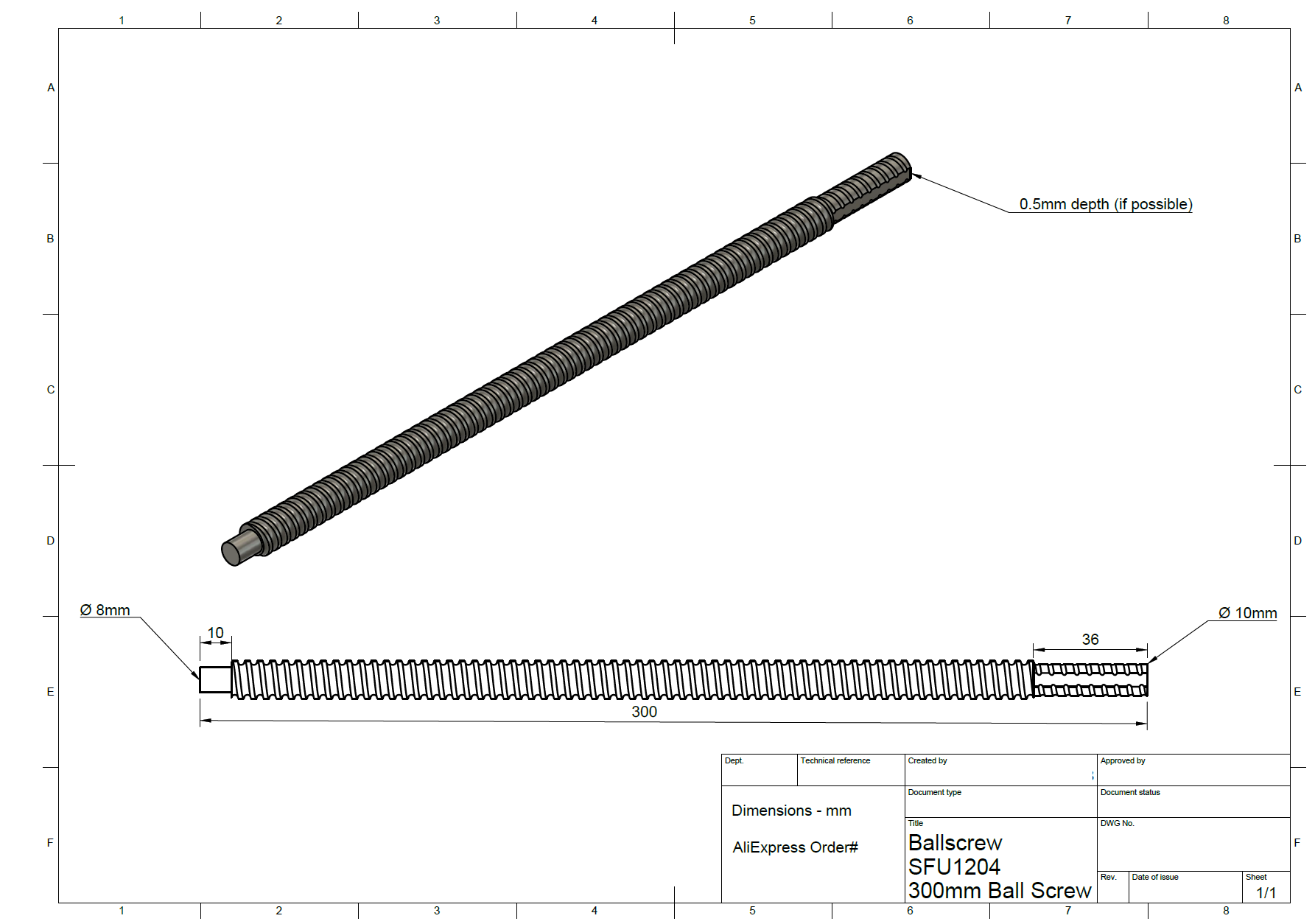
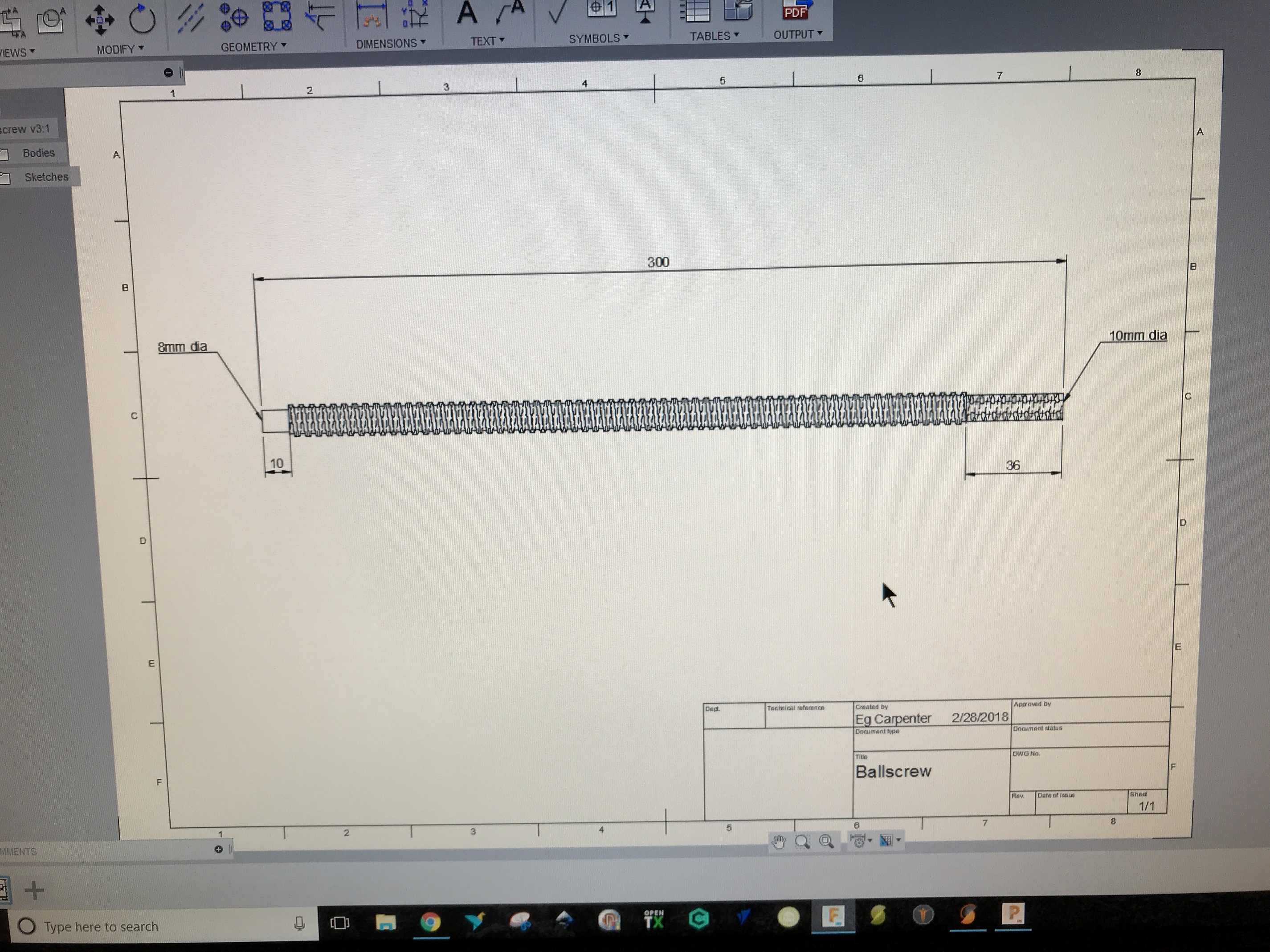
This is the drawing I submitted to them. I’ve no idea if they can/will mill the flat edge requested but they didn’t come back to say they couldn’t. Mine shipped yesterday so I’ll find out soon enough.
It was just a case of placing the order and then sending a message to the seller. I originally just sent the dimensions as text as per Luke’s specifications but it didn’t get made before the Chinese New Year holiday so I’d time on my hands. I messaged them again asking if I could change the specs and they said fine and asked for a drawing. One quirk was I had to save it as an image as Aliexpress wouldn’t allow me to upload a PDF.


 .
.