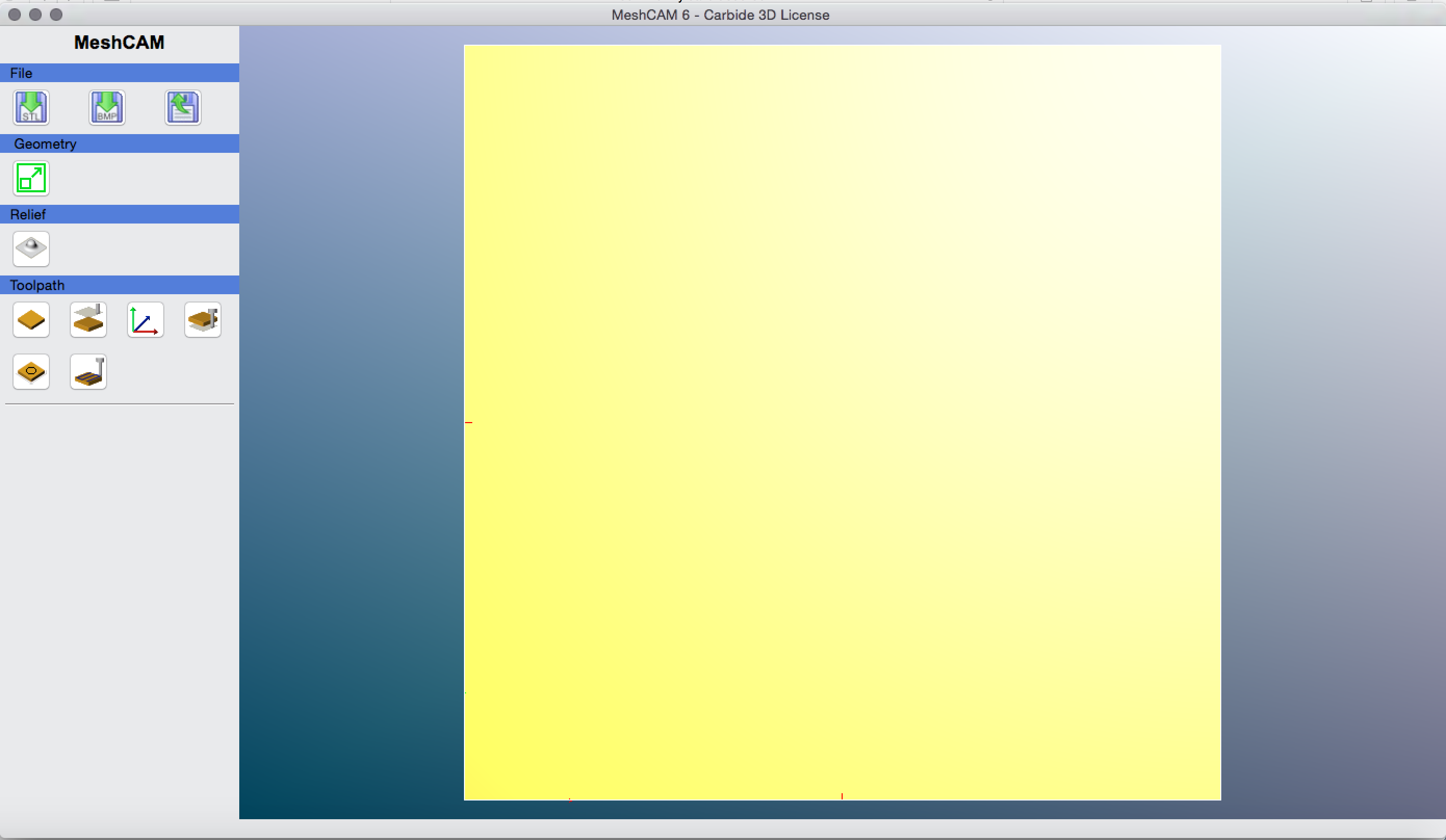
Okay - here is my workflow that I think is simple enough to follow  It may not be the best way to do things, but it worked well for me.
Step 1: Import an image of a black square and set the size to 8" x 8" x whatever (I’m not sure this matters since we will be changing it shortly, but I set mine to .35") Also check “Black is Z+”
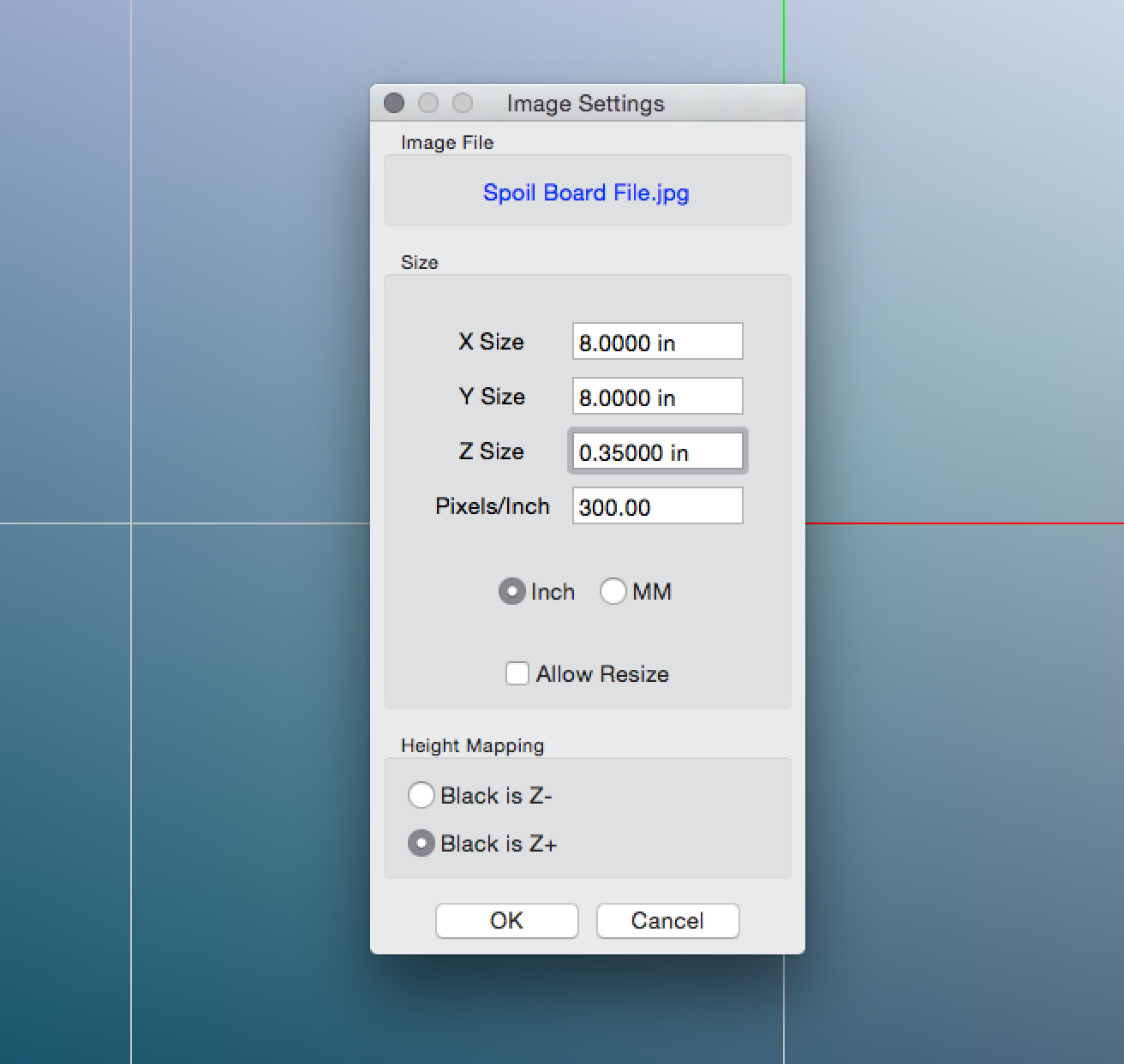
This is what you should see
Step 2: Set the stock size - this is the size of your wasteboard. Set it to 8" x 8" x .35" (although the Z height isn’t as important since we are going to set the max cut depth shortly). Click “Lock stock dimensions”. Also set the Z to zero, so the image is at the top of the stock
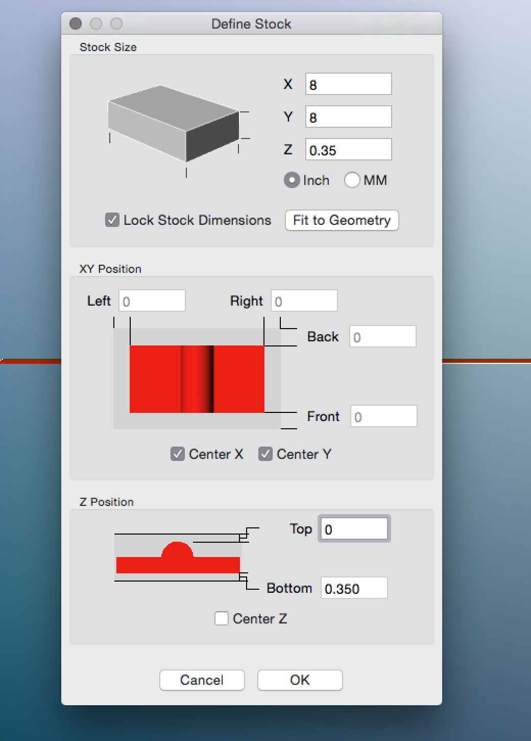
This is what it should look like now

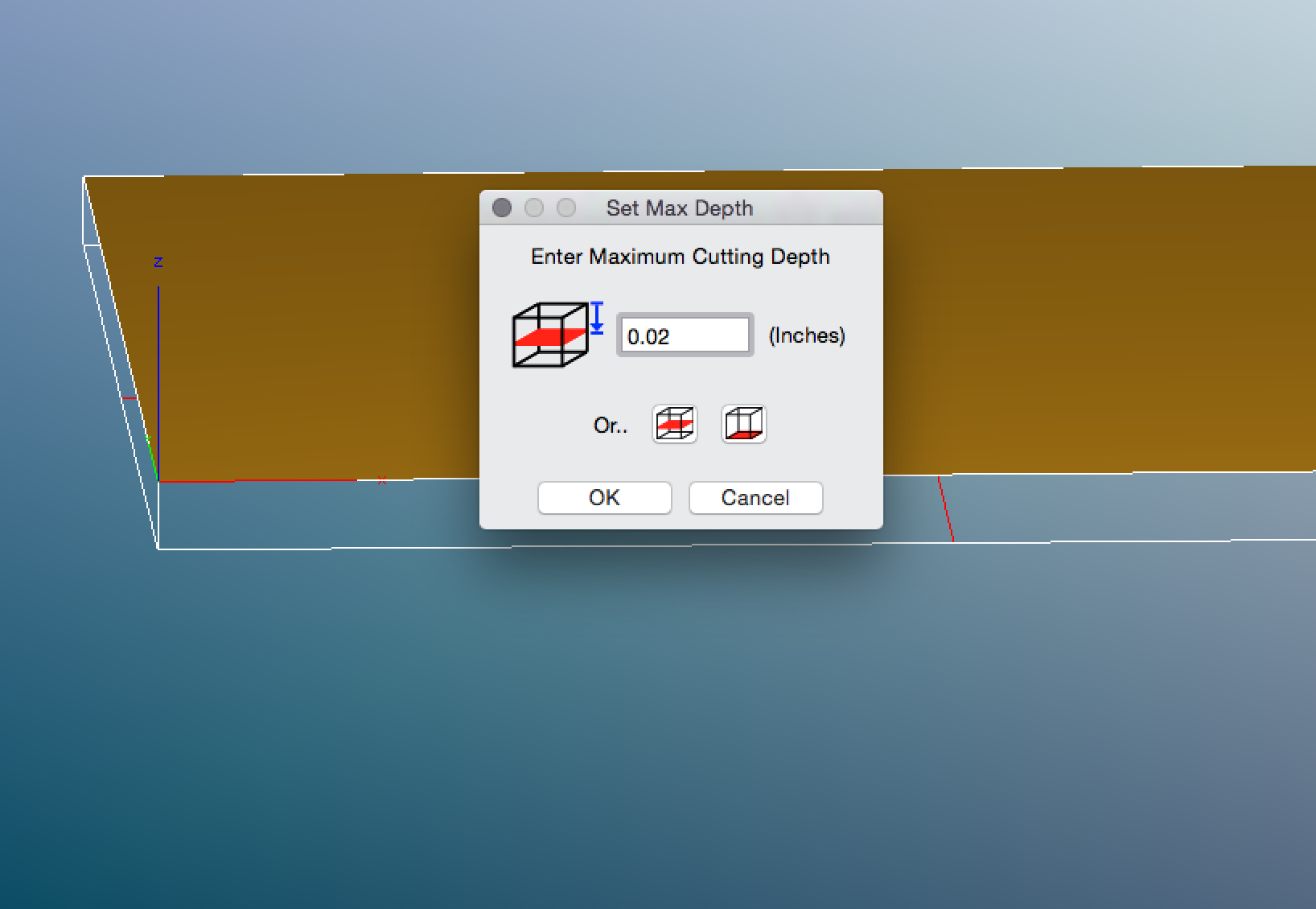
Step 3: Set the max cut depth - this is the amount of material you will be cutting off of your spoil board. I have set this to .02" and it has worked well for me
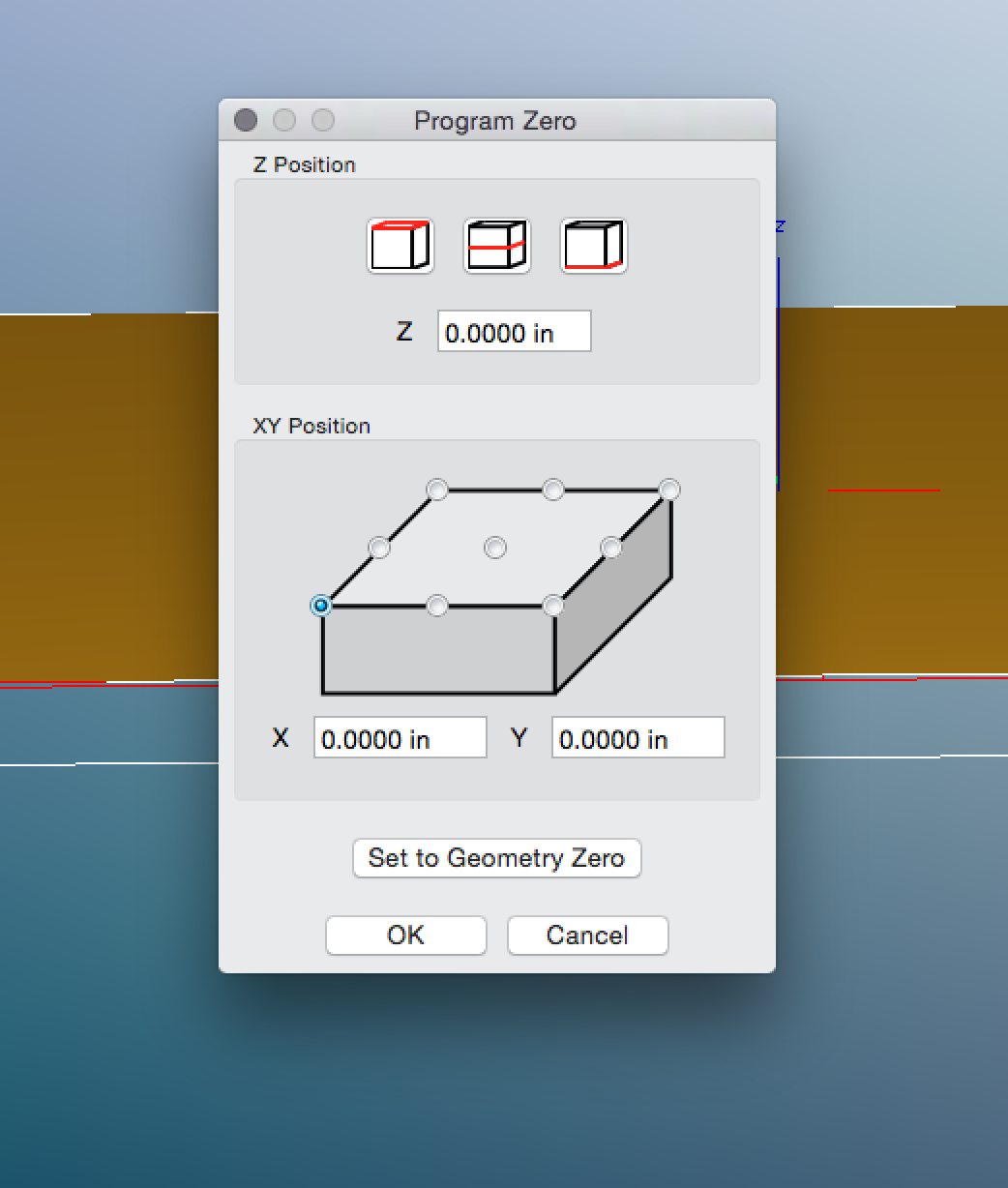
Step 4: Make sure your zero is set in the right place, as shown in the pic
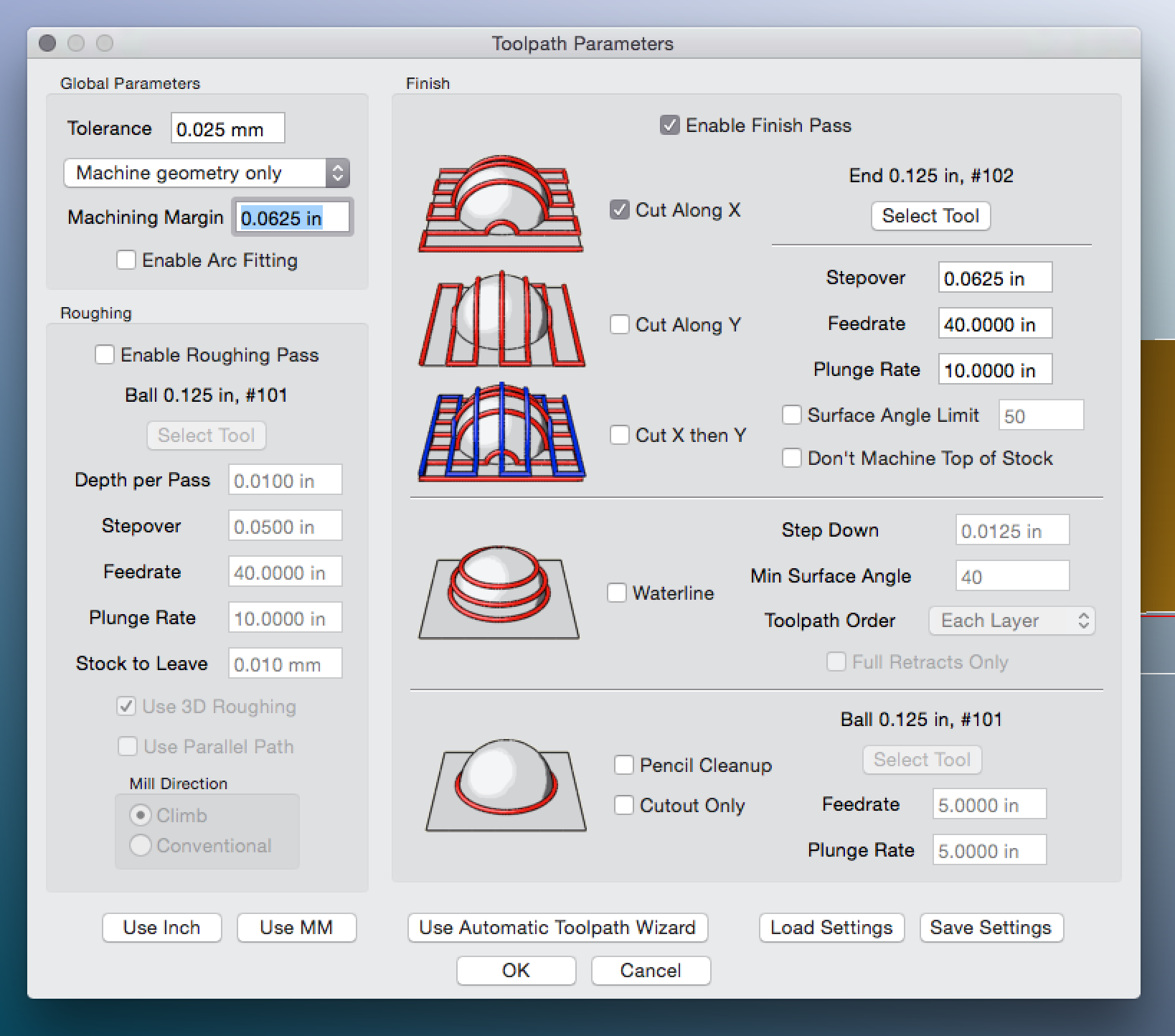
Step 5: Set your machining parameters. Here you don’t want a roughing pass or anything else - just “Cut along X.” You don’t want to set the machining margin too large or else you could hit the tool probe - I have used 1/2 of the cutter diameter in this case. The feed of 40ipm should be fine, and the depth per cut of 10 is fine too. I think a stopover of 1/2 the cutter diameter (in this case .0625) is fine.
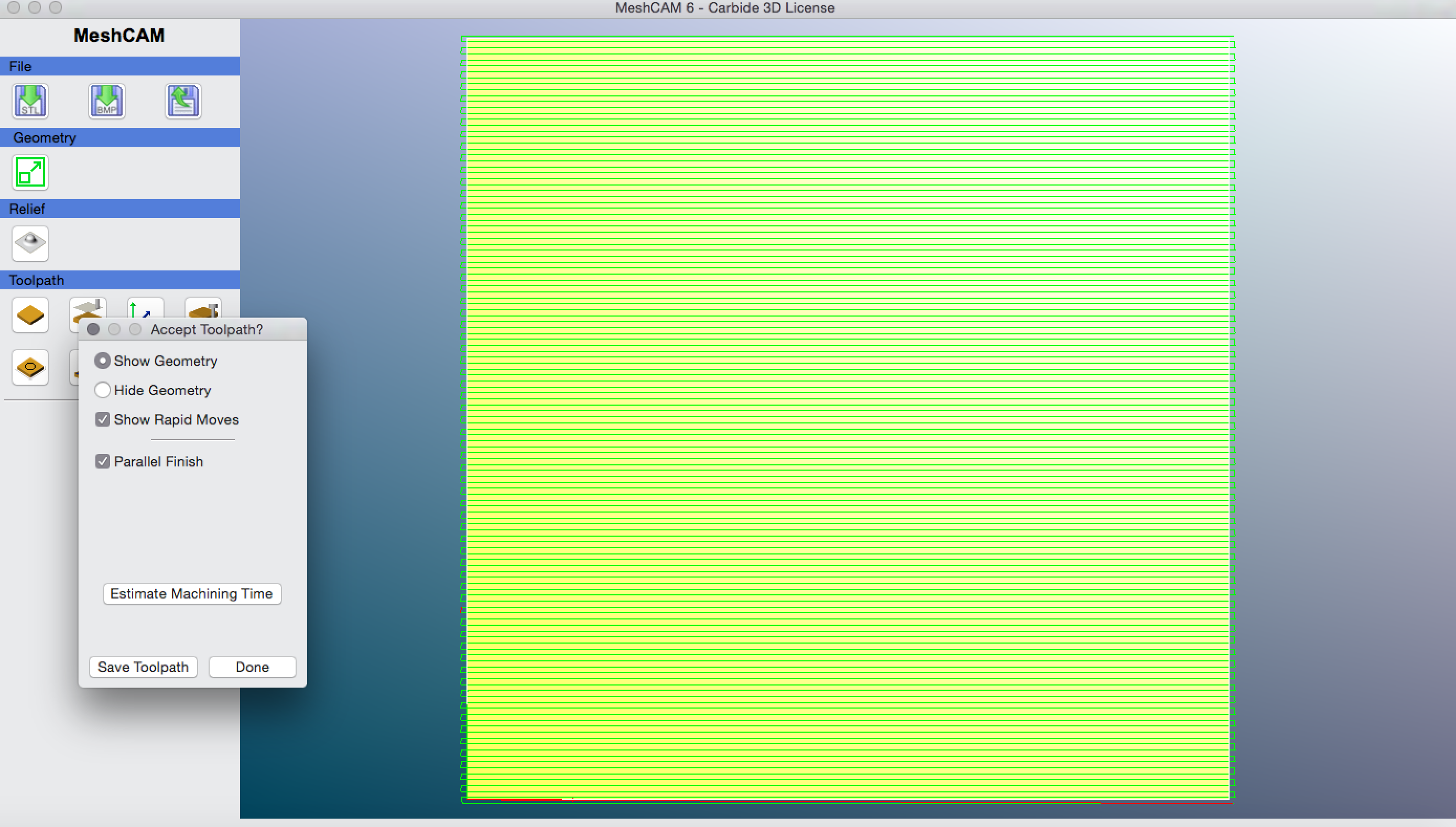
This is what the path looks like
From here, all you need to do is make sure you zero the machine properly. I have a way of doing this that’s not so easy to write about - I think I’ll need to shoot a tutorial video soon