I’ve worked on this some more, and I still have not found decent results (in software), and so I have not attempted to actually cut the part. Perhaps others on the forum with more experience can chime in, but I do not think I can cut this to standards that I would consider acceptable.
Some more thoughts and images:
The smallest ball mill I tried (in simulation) was .0625. You might be able to get more detail from an even smaller end-mill, such as .0312, but those cutters (generally) have a flute length of only about .0625, which limits the depth you can cut. You might have to reduce the amount your text is raised above the surface for that to work. That would also make the part take a very long time to cut, and those tiny cutters are very fragile, so you might risk breaking a bit in the process.
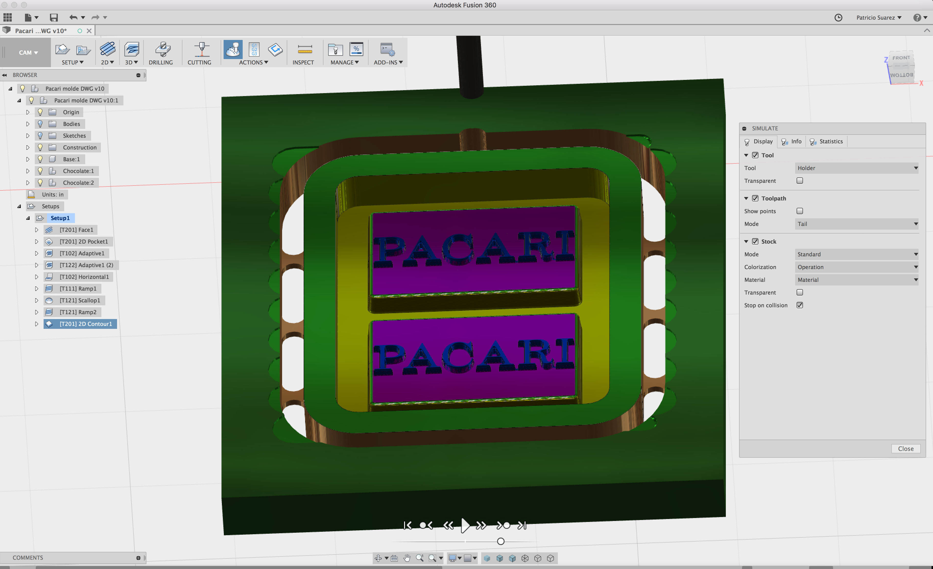
I ran a second VCarve simulation, and tried a few different tool path strategies, and it came out about the same as yesterday:
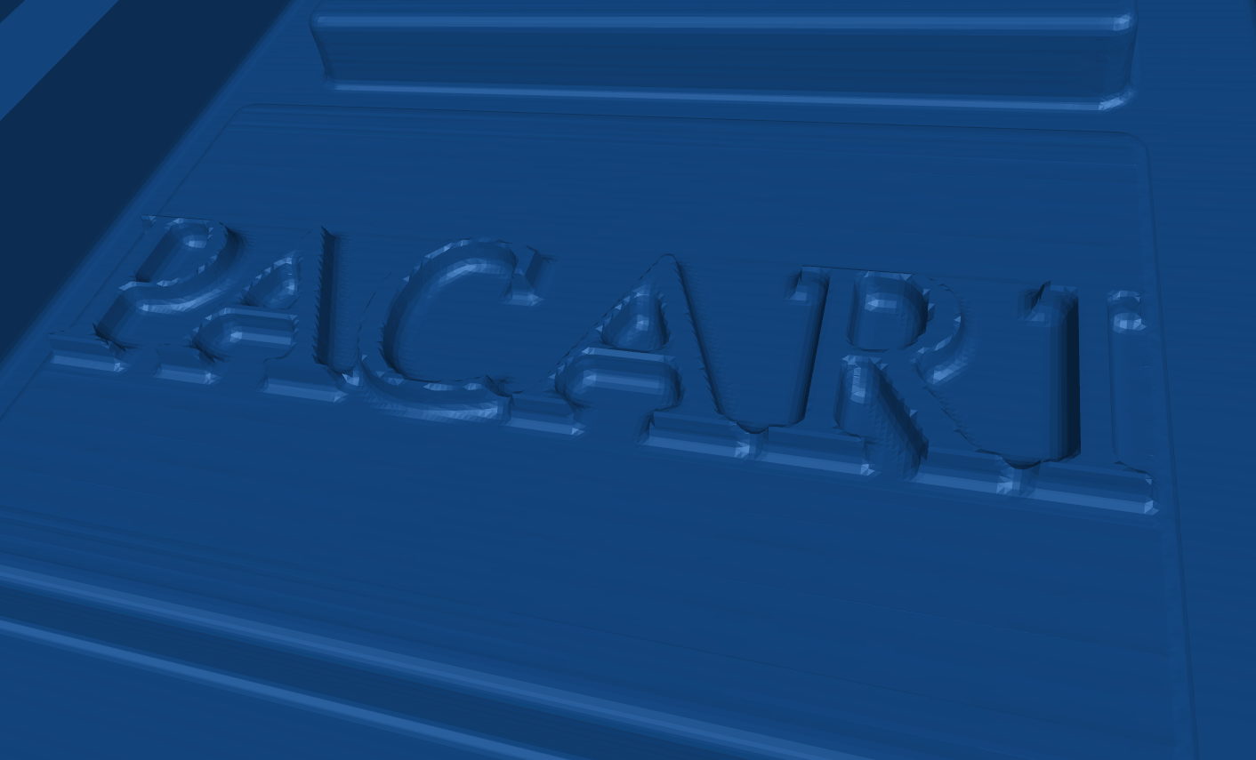
I also ran it through MeshCAM, exported the gcode, and simulated it in CAMotics. My instinct was right that MeshCAM handles it better, but there are still bridges left in spaces between letters where the .0625 cutter cannot reach into:
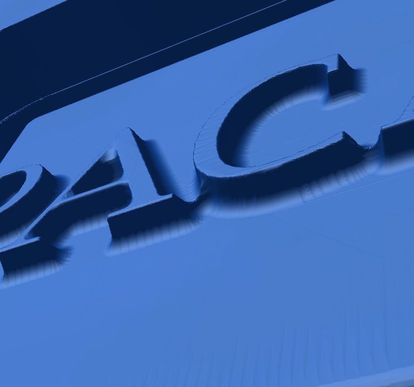
Note that some of the noise in the mesh above is due to the simulation process and wouldn’t actually be in the cut part – but the bridges between letters and the more rounded inside corners of where letters stick up would be in the final cut piece.
I tried a couple of v-bits out of curiosity. The steep angled sides of the lettering come out cleaner, without the waterline scalloping, though their angles match the bit, which is a little different than the angle in your file, and the surface finish is garbage. There may be an advanced tool path strategies that uses a V-bit for the edges and a square end mill for the surface finishes, but that starts getting complicated for what is a fairly simple part.
Have you considered 3D printing it, rather than carving it on a CNC? There are several 3D printing services on the internet that have reasonable prices for high-quality parts. 3D printing would have the advantage of not leaving any step-over scalloping, and if you printed it with a very small layer height, would likely get a smoother result on some of your small details than with CNC.
I honestly don’t think I can help much further. I don’t have any .0625 (or .0312) ball end-mills, and based on my simulation results, I don’t really think it would be worth buying them for this project. In my opinion, you’d be better off 3D printing it, unless someone else on the forum with more experience can chime in and suggest techniques that I am not familiar with.
There are a couple of minor problems with using the .0312 bit:
First, VCarve does not simulate flute length, so what it calculated would not actually be possible to cut with any bits that exist in the real world. I’d have to take several passes with different bits, stepping down in size and limiting the area each bit was cutting to make that work. I’d also have to make sure that the lettering “height” was no taller than .0625, the max depth I think I could cut with a .0312 bit.
Second, the cutting time with the .0312 bit was estimated at 6 hours 20 minutes. That’s not a problem, per se, but it does make me nervous that finding the right feed and speed to get good results and not break tiny bits during a 6-hour cutting session would be challenging.
I still believe you’d get the same results as this with 3D printing, without a lot of the challenges.
Hi Tchad. Thanks a lot for all the great info. In facti work with 3d printers (have a 3d printing business). I have been using them for a whole for this purpose but have some limitations. That’s why I was trying CNC instead. But thanks for all the info. It helps me in deciding whether to buy the CNC or not.
tchad,
I would recommend a tapered ball nose end mill. I have not opened the file to see how tall the lettering is or how large it is. These may work in this application. Typical taper on mine are 6.2 degrees, however each mfg will be different, you can get 1/16" TBNEM with 1/4" shank for around $40, they have approximately 1" cutter length. My son uses them all the time on 3D carvings and produce excellent detail. They will not produce a vertical wall, it will be limited to the taper of the bit.
For roughing, In V-Carve toolpath section, select 'Use Larger Clearing Tool" and use a 1/4"" or 1/8" square end mill for roughing,
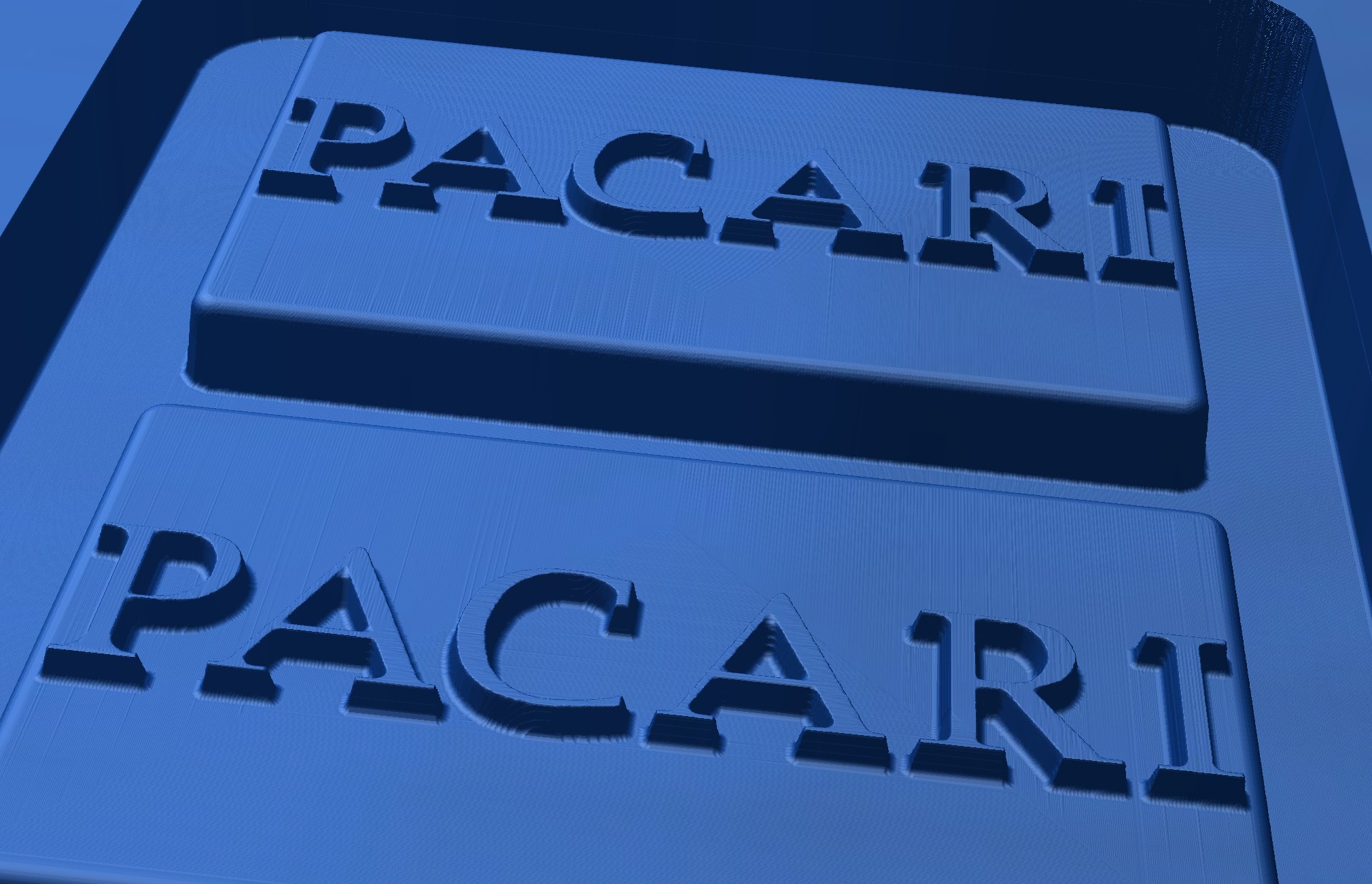
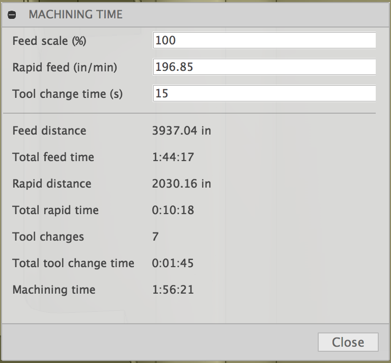
I simulated a 1/32", 6.2 degree taper ball nose in VCarve. (Based on one I found at Precise Bits). The results are somewhere between the 1/32" straight bit, and the 1/16" straight bit, decent, but not good enough for a chocolate mold:
The good news is that it’s way faster. Total machining time is 1 hour 20 minutes (which I’m a little skeptical of, but I didn’t scrutinize the feed rate of the taper ball).
The “User Larger Clearing Tool” option in VCarve is limited to the pocketing tool path. Since this is a 3D part, I instead used the “3D Rouging” tool path, followed by the “3D Finishing” tool path. I roughed it with a 1/8" square end mill, because if I use a 1/4" bit, the finishing tool path takes longer than the additional amount of time the 1/8" bit runs.
@jdg3 That’s a good point. @JamesC’s dies also have similarly small details, so clearly there is a way to cut this part with high quality. I recall @JamesC saying these take on average about 8 hours to cut, which is perfectly reasonable for a part like this, but also beyond the amount of free time that I have to spend running a test cut to help someone out right now (sorry!).
What is the stopover you have set from the endmill? From my experience you should be able to achieve an acceptable finish with 4-6% step over on the endmill. If the preview is still showing scalloping, reduce the step over until you achieve the desired look.
If you want to clean up the sides of the letters, take a look at Vectrics tutorials on Rest Machining, this is a method to create vector boundaries to work on specific areas and clean up tool marks.
You can also increase the feed rate on the tapered ball nose end mills, they are not as fragile as a smaller standard endmill.
I get that, for sure.
I was just throwing out some ideas.
When I was using Artcam, I could machine the same model more than once, and each time, I would use a different Finishing tool, and no roughing, running the simulation after each tool.
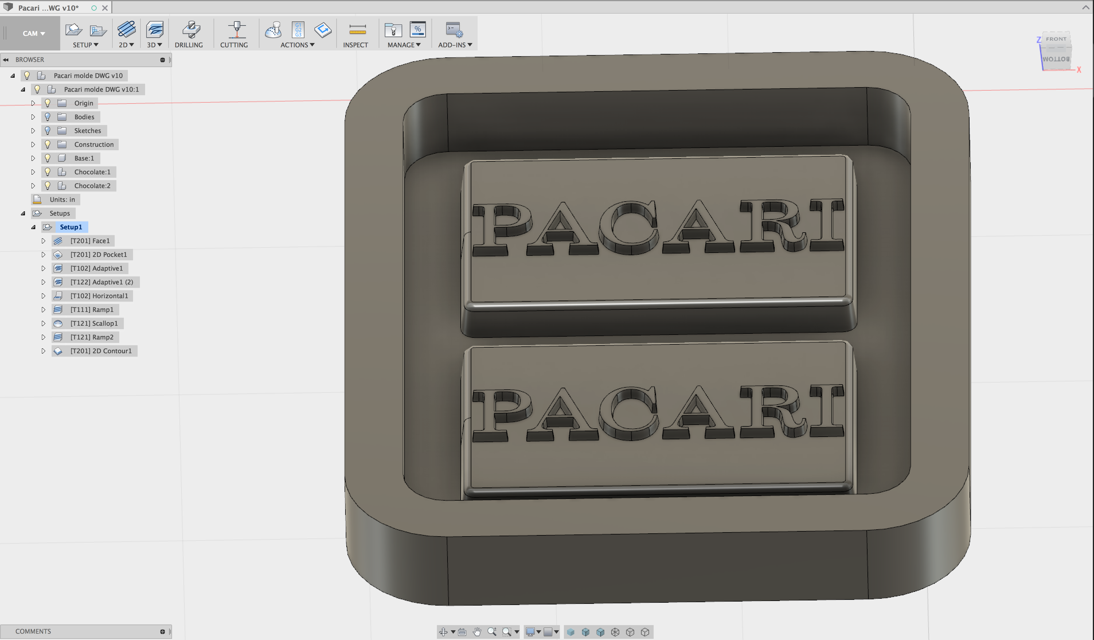
I’ve spent a good chunk of two days trying to get this model into a millable state in Fusion 360. My problem was that the STL file produced too many triangles and it became almost impossible to work with the model with my computer. I proceeded to model the easy parts and got as far as the letters. I tried different methods and got nowhere in an efficient way. I decided, for the sake of getting a milling quality and time estimate to model the words myself using another serif font that would give me an idea of what I had to do. My conclusion is that I don’t have the tools/experience necessary to mill this properly. I think I agree that a hi quality 3d printing machine might be better. Sharp inside corners are a limitation of CNC bits. Maybe with the right v-carve bit?. My estimate is about 2hrs (not bad) but the quality is not ideal.
I am getting good at milling but my confidence is not that solid to know I can get this done in a timely fashion. I am interested in learning so this process of figuring out how to make this work has been good and productive.
Either machine is capable of what you desire.
It depends on the CAM, and the persons skill level with that CAM.
I can give some pointers to help you choose.
I don’t have the Nomad, but I’ve built a lot of machines in my life, so I can give an estimated guess.
Unless you live with your machine, and keep a good eye on calibration, then I would say the Nomad will be the most accurate, and sturdy for it’s size, and the most maintenance free.
What I don’t like is the slow spindle speed.
A machine that small, doing that small of work should be able to go 3 to even10X faster. It’s the reason, I believe, people brake small bits on it so bad, and have such long machining times.
If you can get the Shapeoko dialed in good enough for you, you will have a lot more room for experimenting with the right feeds and speeds.
The finest finishes (in metal) have a fast rpm, shallow cut, and slower feed.
Being as you are doing plastic, I’m not sure the RPM speed will benefit you at all.
In that case it would be the Nomad for sure.
You might even consider a fast, low res, 3D printer (cheap), then do finishing work with the Nomad. Similar to machining castings. I don’t know how many you plan to make in the future.
Thanks Jerry. I make a living working with 3d printers so that is an area I know pretty well. However CNC mills are totally unknown to me. I get what you are saying. The issue I´m having is that with 3d printing (because of print area on my SLA machine) I can only print the individual chocolate bars which I then paste to a wooden board using molding paste, let dry and then I pour the silicone over that. However, I do get silicone coming underneath the individual bars, even when I use hot glue (which I hate because it is messy and doesn´t give a professional look). So I traying to CNC instead because that way I can cnc an entire slab of acrylic including the chocolate bars and won´t have the issue of the silicone coming underneath the individual 3d printed bars.
If only you had a Shapeoko. You could mill shallow, tight pockets in the wood, making “shut offs”, so it doesn’t go underneath, like an inlay.
A trick I used to use with plastic mold shut offs (Kiss offs).
Now I’m not sure that would work for you, either. The wood having to be at least a little wider than the bars.
I dont have an image, and I dont work there any more, but basically if you make your bars a little taller (+ the depth of the pocket), put them in the pocket (a snug fit), then the silicone wont flow in, and if any does, it’s just a little flash to clean up, but it probably wont.
Heck, I guess you could print a tray too.
Thats a fantastic idea. I can laser cut a whole grid and then fit the bars into this grid of shut offs. That way I also make sure the bars are aligned correctly to fit on my client´s production line.
There is a Vectric how-to here that explains this technique. Of course, you don’t need the Vectric how-to to do it on a 3D printer, but it does at least demonstrate the principles involved.
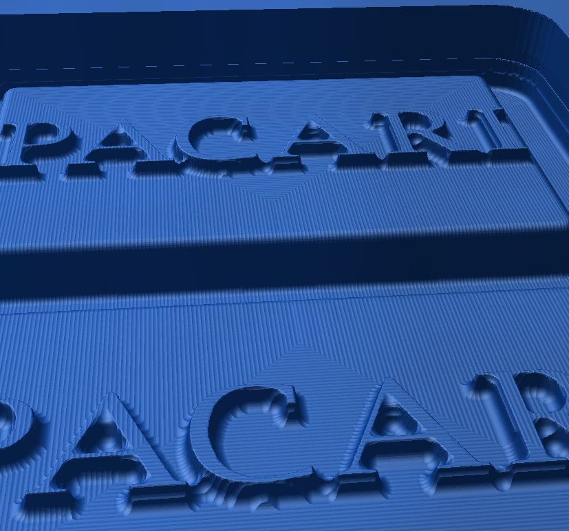
The step-over was set to 20%. I re-ran the simulation at 4% to see what would happen (in VCarve).
You’re right that the scalloping is dramatically reduced (see image below). The bridges between letters remain though (likely because the taper bit cannot reach into those areas without cutting into the tops of the letters) and there are strange artifacts along the edges of the lettering (likely due to the pixel-based processing that VCarve employs).
The job time went up to about 5.5 hours with a feed rate of 40 IPM. I didn’t check G-Wizard to see if that is at all realistic, so reality could be longer or shorter.
This was a fun exercise to figure out how to best carve this part in theory, but I still believe 3D printing would be easier, and I’m glad @jdg3 had a good suggestion to solve the 3D printing problem @Luismchiri was facing…
is there a dxf file of this some where? My older version of v carve wont bring in an stl. file.
I just cant believe this little 2d cut would take 5 hours.