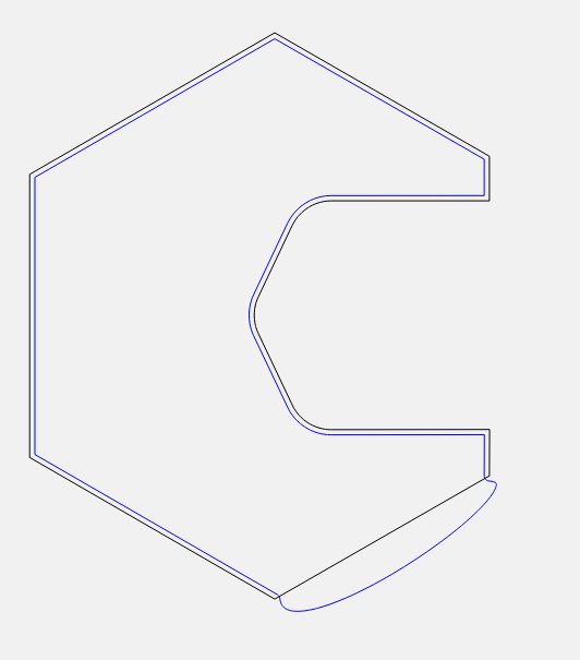
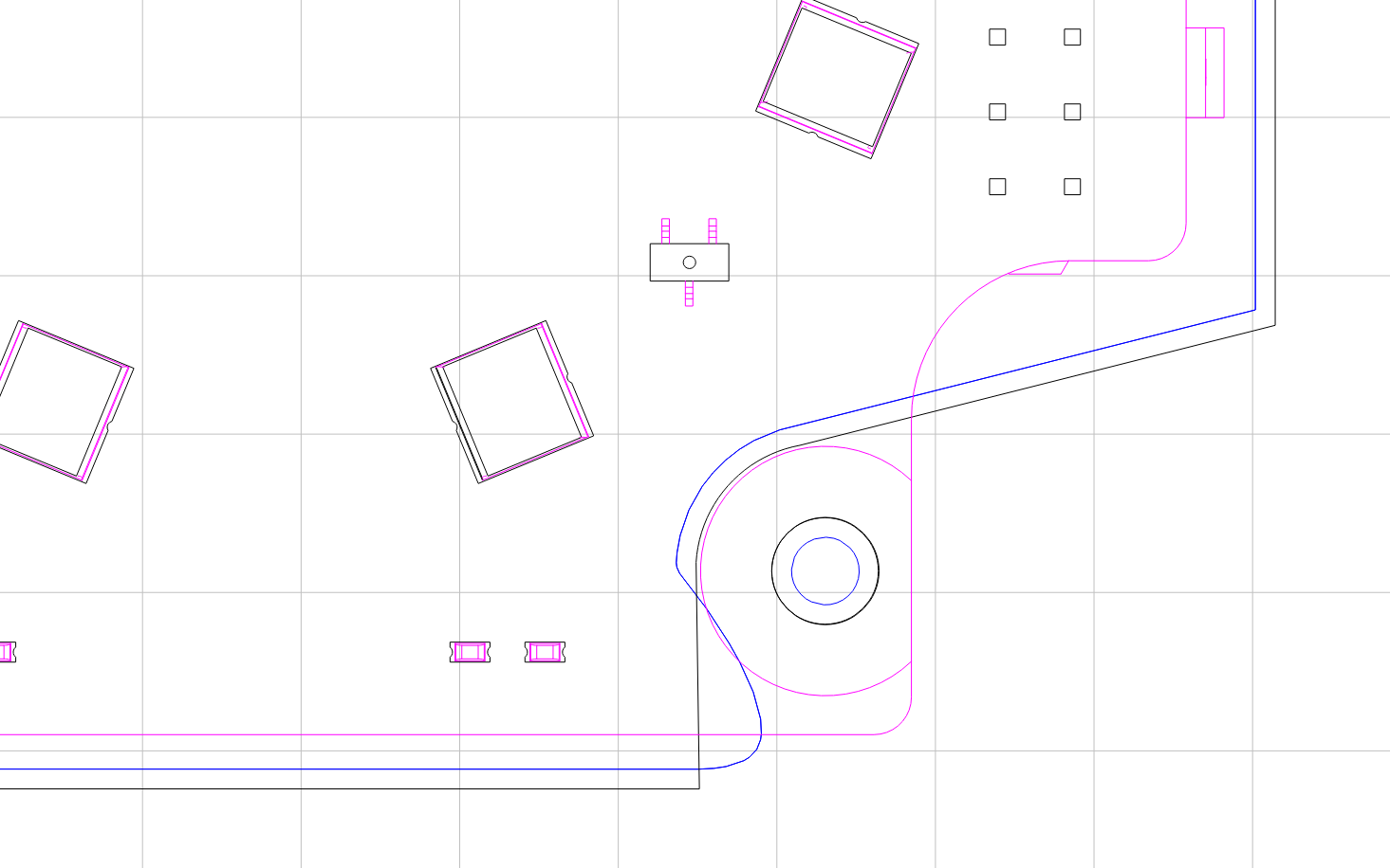
Hi everyone. Just doing up a design in Carbide create today then went to generate toolpaths and have this problem. The toolpath for a straight line element is curved? I deleted the nodes in that area and redrew them which smoothed it a little but didn’t fix it.
The design element is a mix of polygons and freehand “inserted nodes”. My feeling is there’s a node out of order possibly? but I thought it would have been fixed when I deleted and redrew. Anyone else seen this issue or any ideas how to resolve? Thanks,
Travis
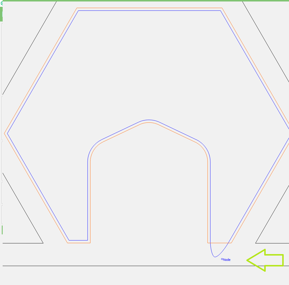
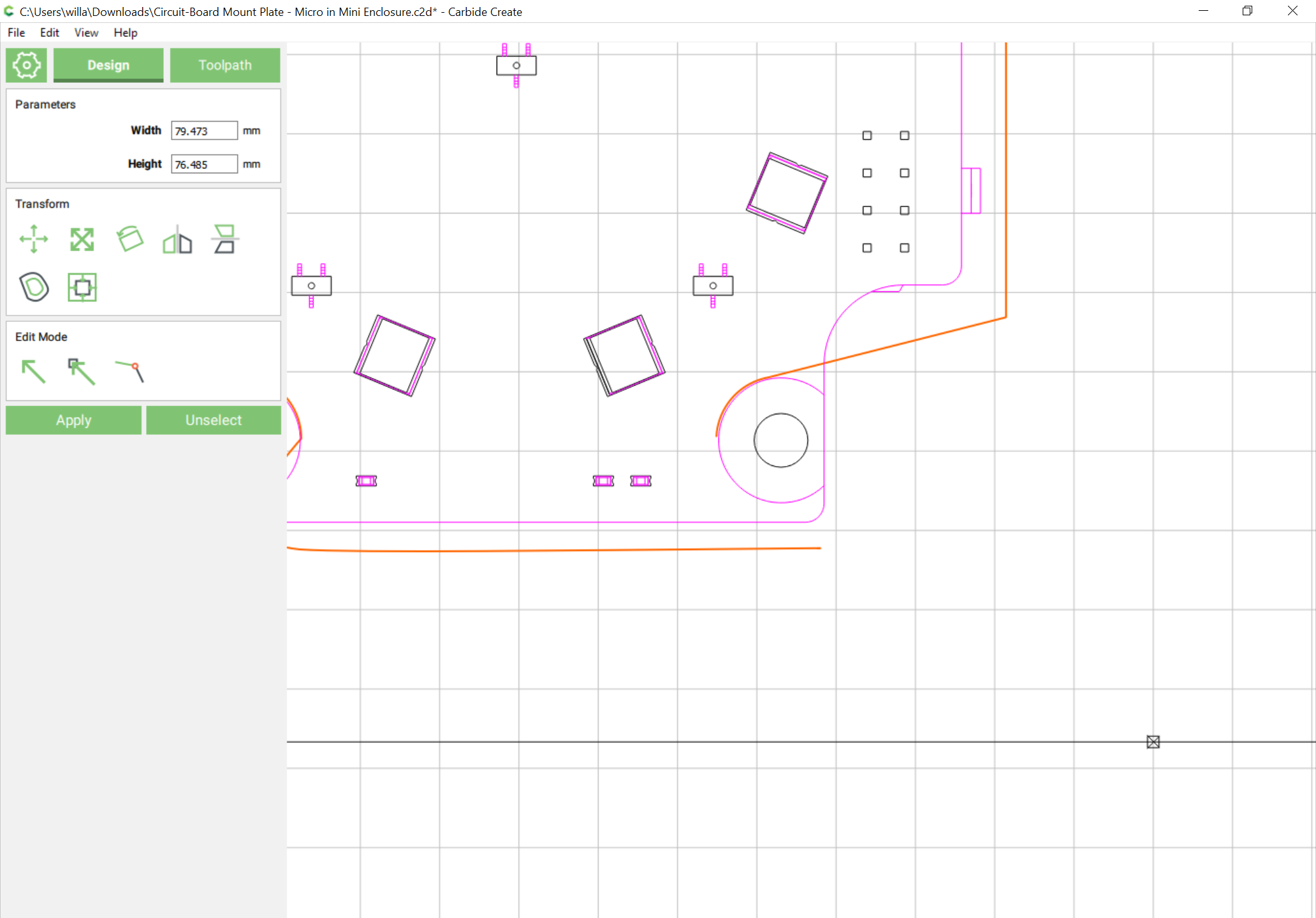
I have a previous version of the file before I redrew the nodes which I just went and generated toolpaths on and saw this - a rogue invisible node? when I try to do node edits it doesn’t show these “nodes”. It’s almost like the little adjustable nodes you get for a Bezier curve out there in space?
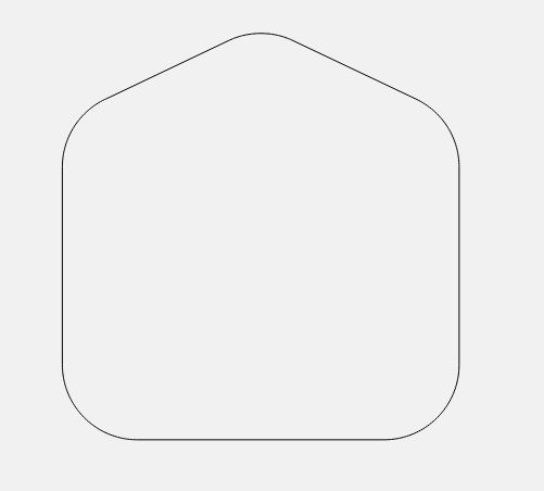
Just thinking through this and I may have worked out the issue although I couldn’t repeat it…
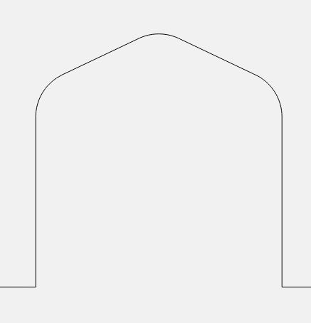
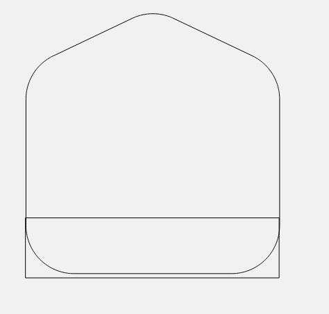
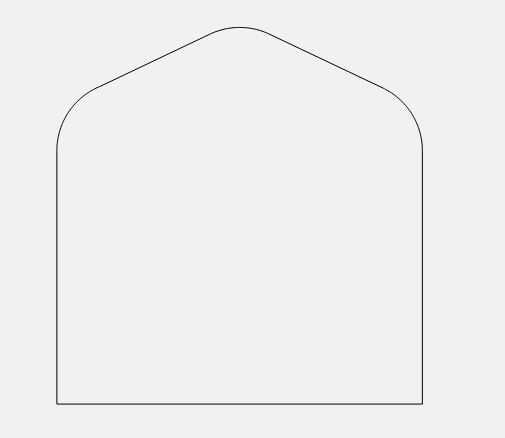
To create this
I created this
Then Boolean joined it with a rectangle
I’m wondering if I inadvertently didn’t have the rectangle high enough and one or two of the original curved element nodes survived? But even then it shouldn’t throw it? I’m not sure. I’ll leave this workflow up to give the developers more info though.
well, I’m not sure why I was running build 316… can’t even find that one on the downloads page… guess I should check for updates more frequently!
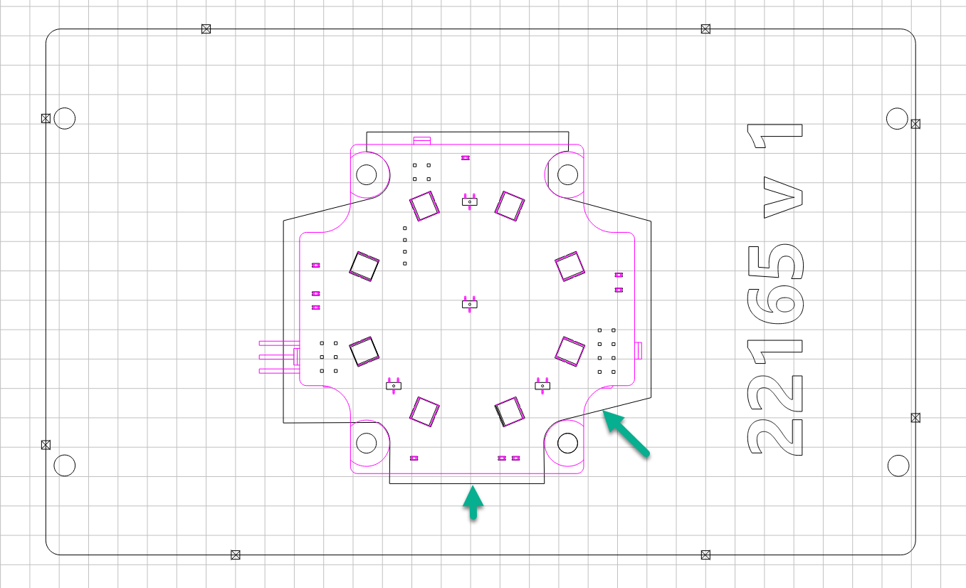
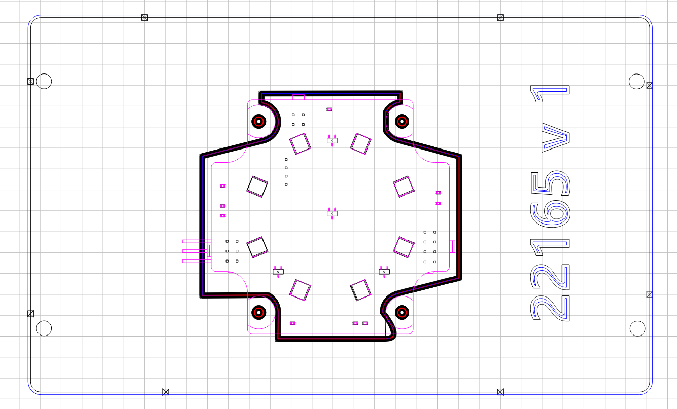
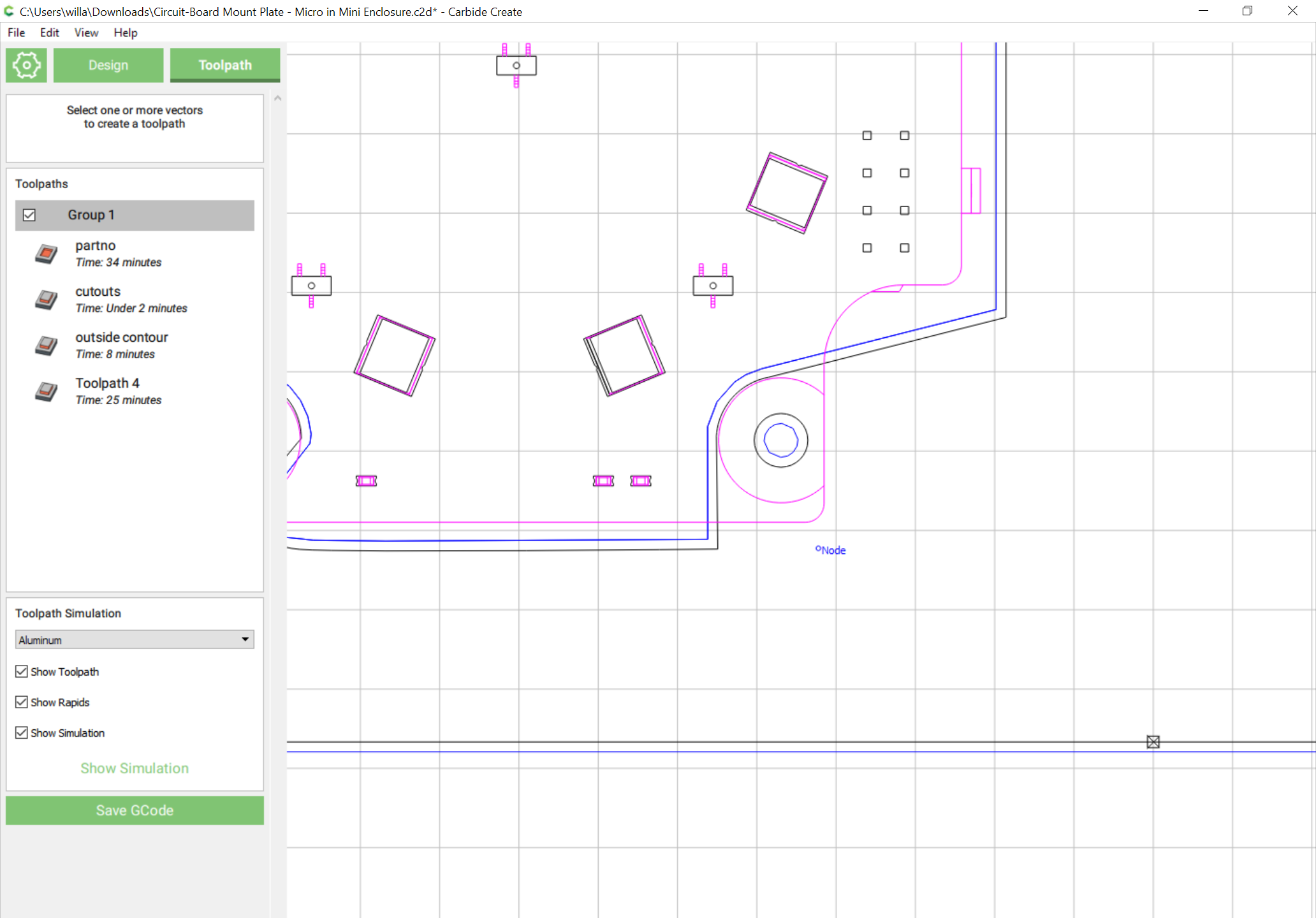
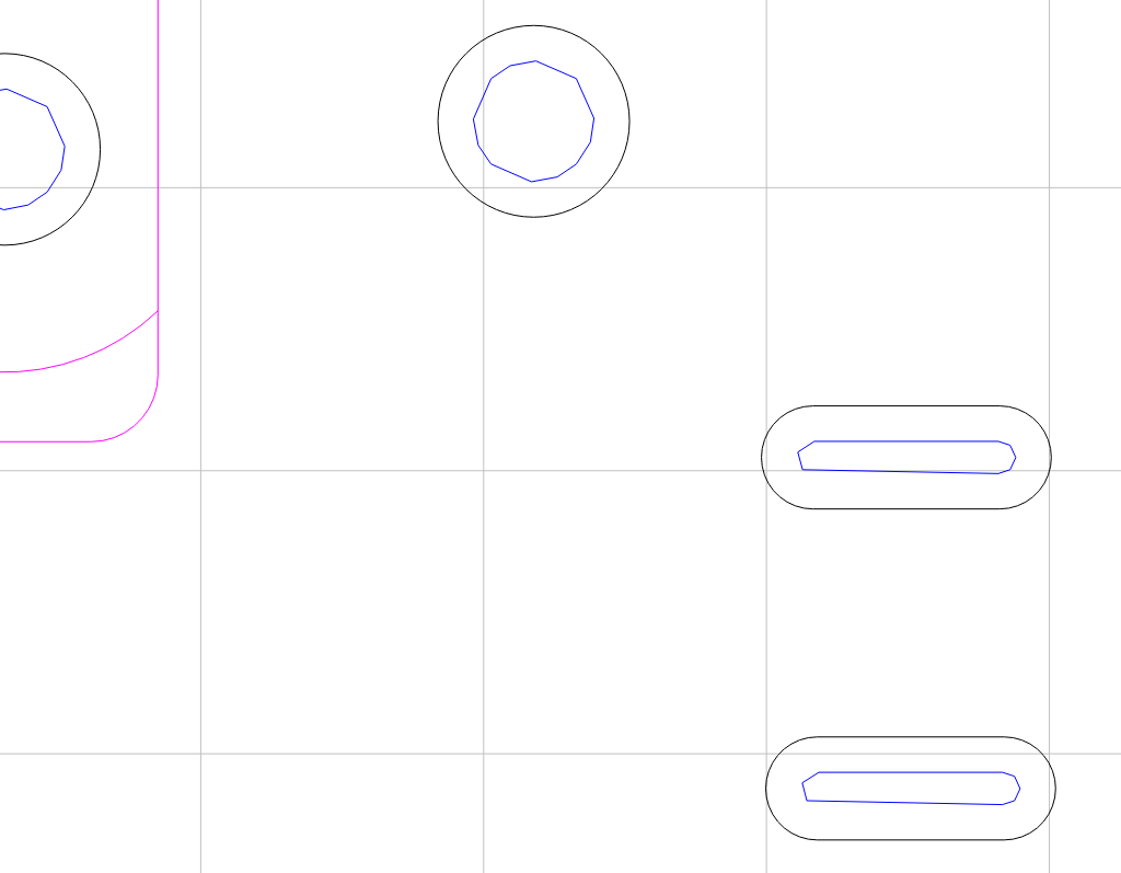
Anyhow, I got myself up to date (now running 431 free version) and I still have an issue. I fixed the missing nodes (thanks) and that fixed my one issue. Now, I’m seeing irregular shapes for the circles and slots! Actually, all the paths are jagged, not smooth - I tried re-creating them with the same results. What am I doing wrong?
I would check the simulation. But it’s more than likely your bit is too big in those smaller areas. To show a smooth toolpath. It will probably look ok in simulation.
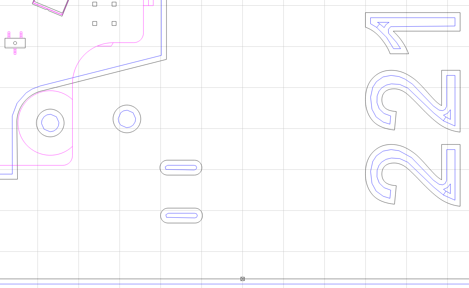
Looking at the file all the circles tool paths are super jagged, more than normal. Have you tried exporting svg and re importing it? Its still going to show up as a bunch of straight lines in the latest version.
just tried that didnt help
Something definitely not right in CC right now… I don’t usually use for anything that has to be exact. Its much easier to design and cut in another program. I just use more for simple stuff.
Hi Will - if you’re monitoring this post, please reply asap, as I really need to cut these parts. And, I’ve been dead in the water for the past ~3 days.
For anyone else seeing this and having the same issue, here’s my c2d file in case it adds to your sleuthing.
good question fenrus and one I thought about, too, but hadn’t been able to pursue yet.
I’ll try to get around to that. But, the toolpaths should still be representing correctly in CC, so my question still stands - don’t let me down Carbide! I keep bragging on you, don’t let me down!
Have you tried to actually cut this? Although the blue tool path lines look jagged, when you look at the simulation the tool path lines look smooth (the lines are green in that view). My guess is that it’s just a rendering issue, since these are pretty small tool paths and you need to zoom in quite a bit to see them.
I would try to cut it in a piece of scrap and see what happens.