Not everything on the Nomad need be the end in itself…
Background:
The zoom adjustment knob on one of my microscopes (Nikon stereo zoom) began to turn freely on the shaft. A little investigation found that the drive is a cross pin through the shaft that acts as a key in two keyways inside the knob. At some point in its life, it had been forced and the material broken out, allowing the know to rotate and wear a groove. It appears that it had been repaired at some point prior to my getting the unit, as evidenced by cement residue on the broken surfaces. I took a shot at re-cementing, but no dice.The cement held, but the material broke of under it.
So, the options are:
buy a knob. Not realistic for a 25+ year old unit. The only one I could find on line was about $US100
Machine a new center for the existing knob: not the first choice, as I work by the minimum modification principle: minimal change that can not be reversed
Machine a new knob: more work than I want to go to at this point. If I need to, I will.
Find a way of recreating the keying action: this is what I did
The repair was done by making a ‘fork’ shaped element from 0.75mm music wire, cleaning up to good material where the keyways need to be, drilling 0.72mm holes properly s[aced, and pressing in the bent-wire forks to act as keyways. The reasons for the fork form rather than just shoving in pins include stiffness and resistance to losing the repair part inside the microscope objective/zoom assembly.
The bent part needed to be dead on size. So, I made a jig.
The machine work:
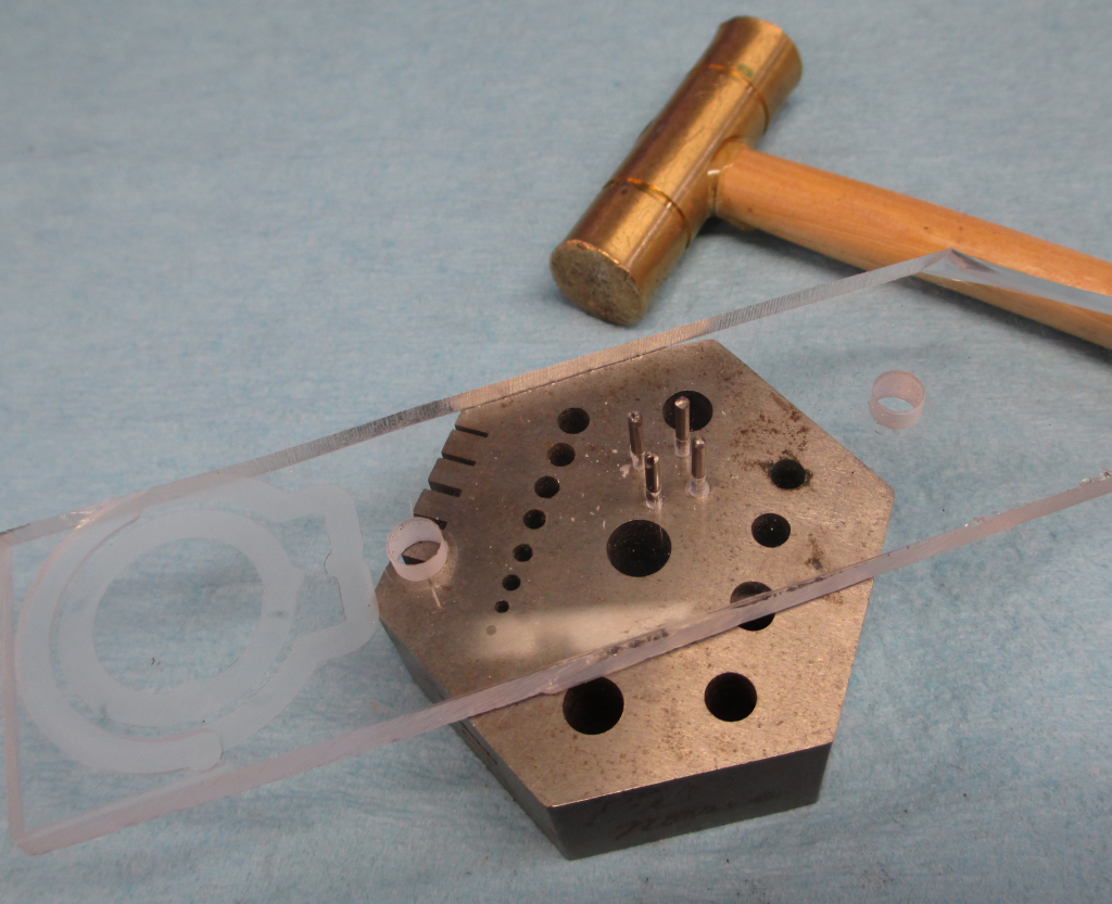
The bending jig was made from a spare hunk of 5mm acrylic sheet and some 1.4mm pins. I modeled the holes for the pins in inventor:
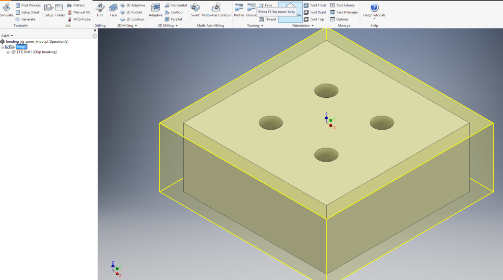
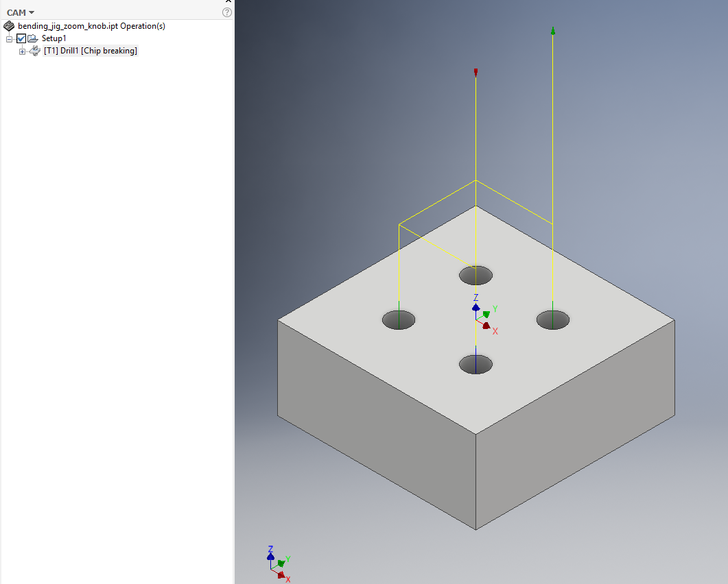
Looks simple, no? but it needed to be right on size for the part to fit. The modeled hole is the 1.40 pin size to get the proper spacing for the centers, but the drill was 1.37 to allow a force fit. I used the top surface as my Z zero and the drilling was a peck operation for chip clearing and keeping the bit cool and clean. Acrylic likes to melt onto the bit. Ran about 0.015mm/rev feed, turning at 10KRPM. Pecks were 1mm, decreasing by 0.05mm to minimum of 1mm. The drill operation was for break through by 0.5mm.
The finished machining (no shots during the run… I only took about 45sec):
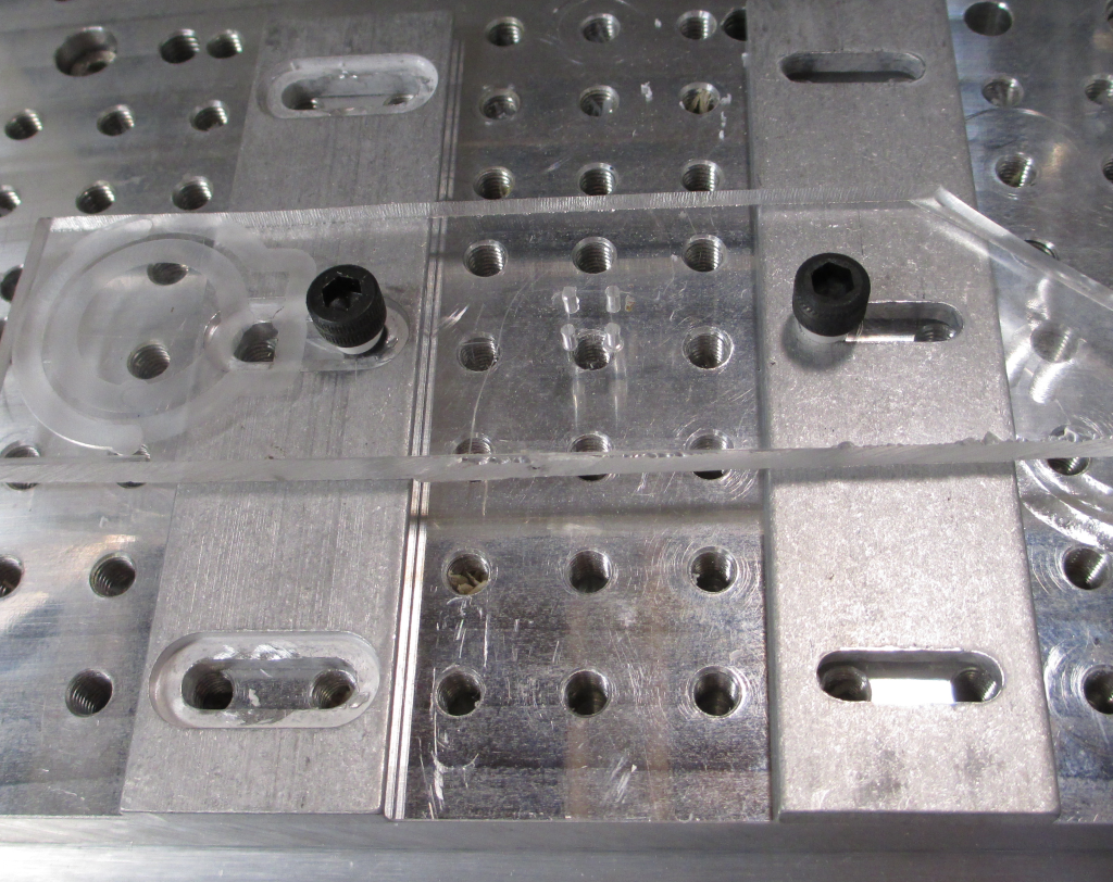
The material was just bolted down on spacers through oversize holes.
The result:
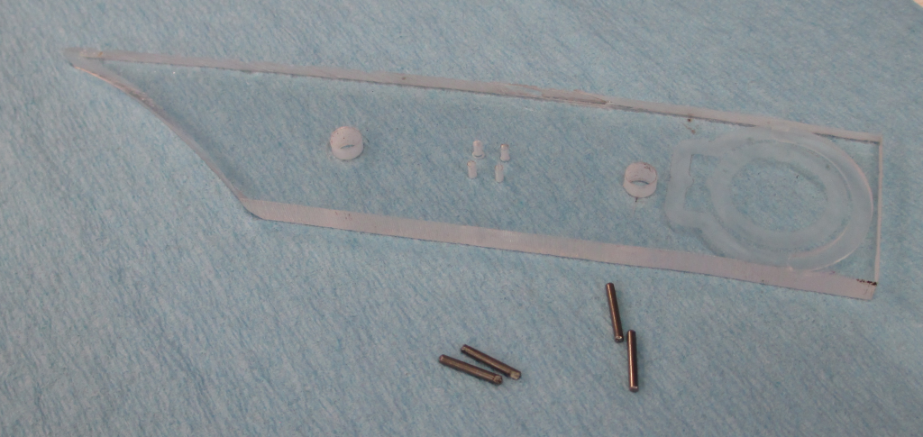
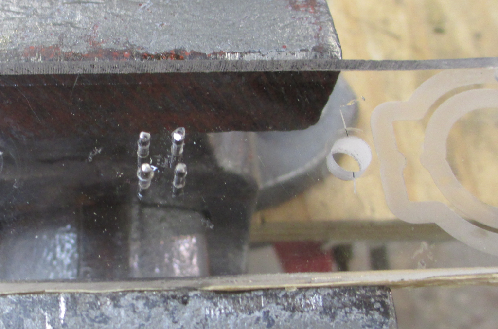
The part and the pins (previously used hard dowels)
tapping the pins in. At this size, and acrylic, 0.03mm is a nice force fit. The pins won’t slip (ever. I have used this fit on parts that are 20 years old), but won’t cause cracking or significant raising (extruding a pimple around the pin) of the material around the hole.
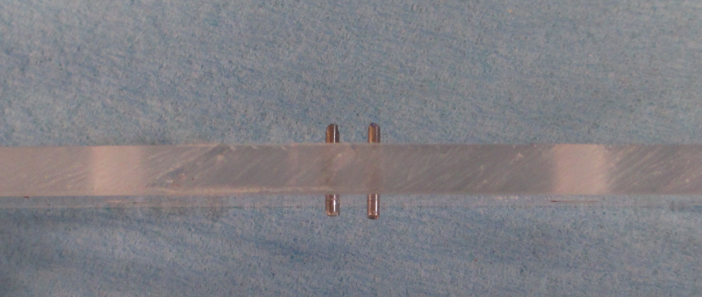
The pins are not all the same extension. This is to make bending easier.
Bending the wire:
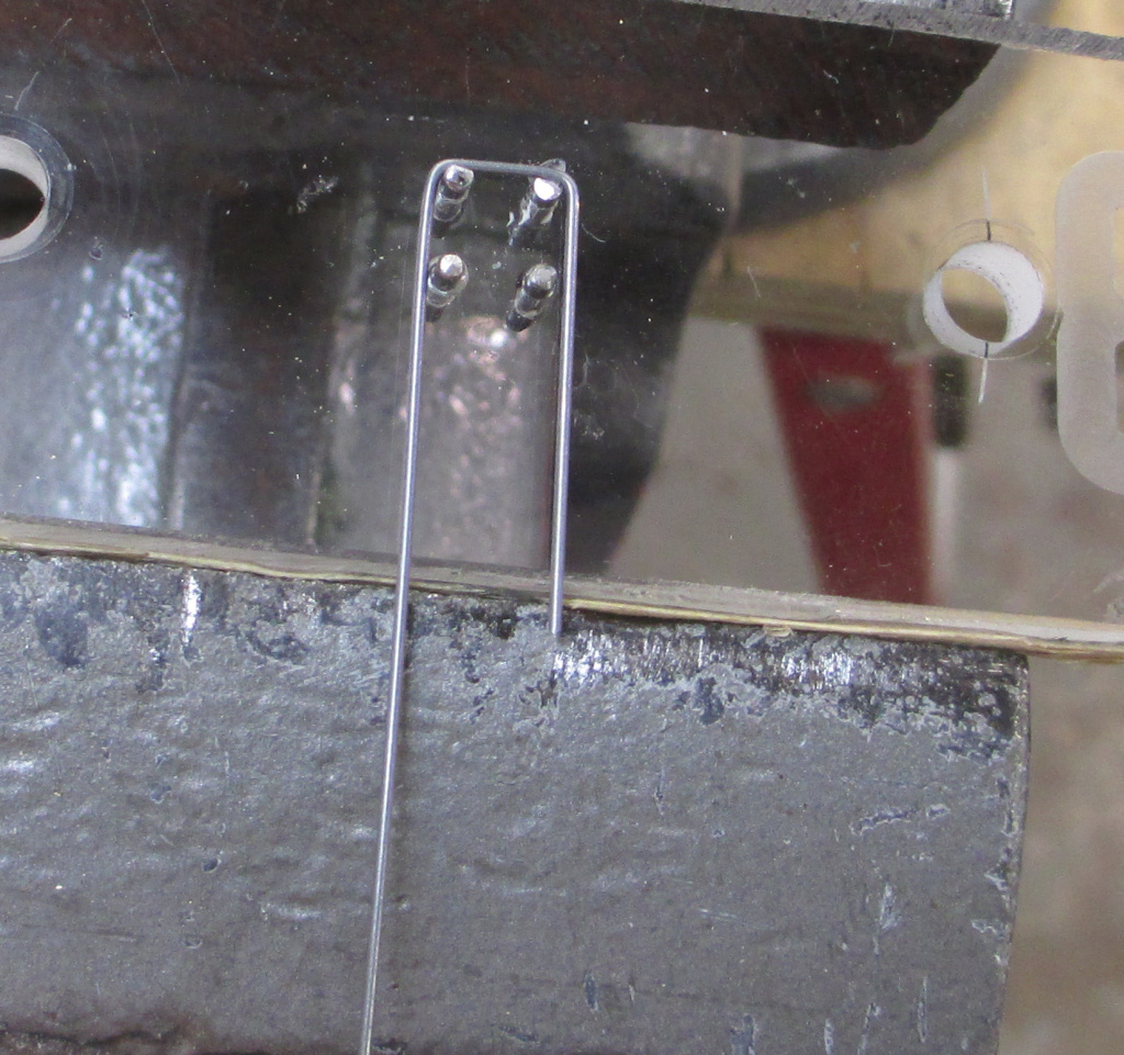
Just held the jig in the vise level with the top of the jaws and went to it using hands and pliers. At this scale, magnification is useful. The fit of the pins in the acrylic is quite fine to keep the pins positioned for the appropriate dimensions in the part.
Final part and installed:
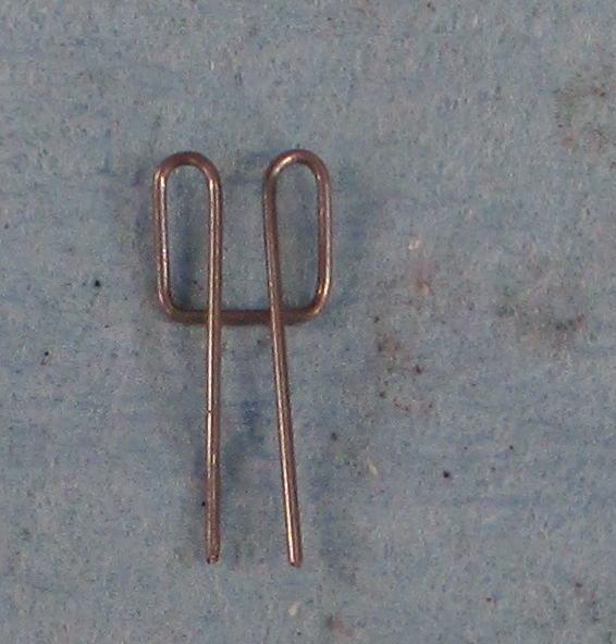
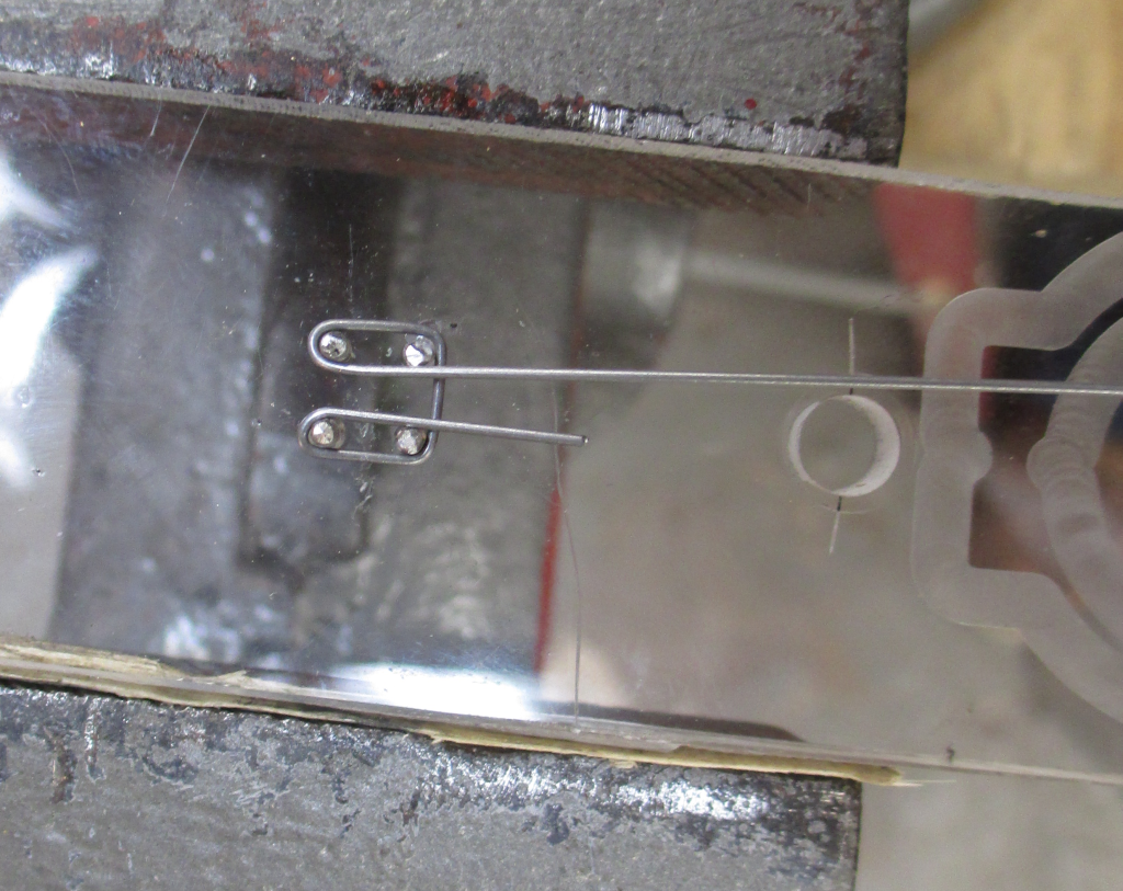
Clean shot of the final part (one of two).
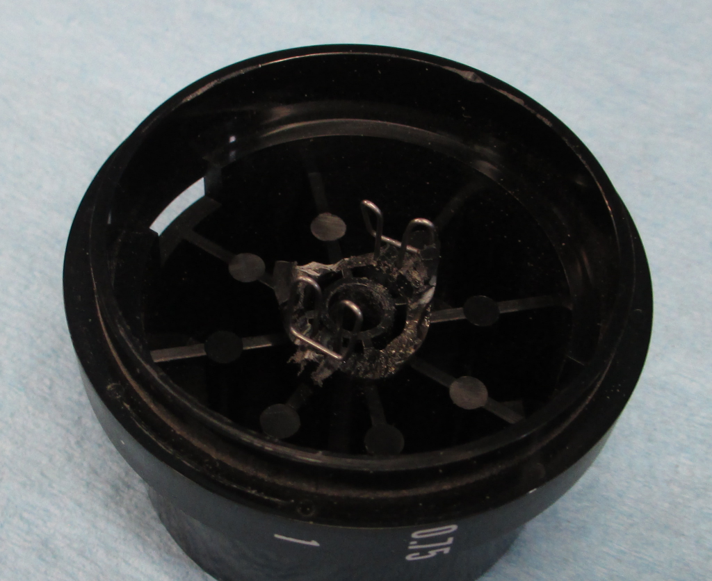
The two parts installed. It turns out that it is really hard to get a good shot of this, but the fit is visible, as well as the original damage. Where the legs of the parts enter the holes, the flattened surfaces are visible, as well. I have no pictures of machining these and drilling the holes, as I did this on a different machine.
It fit the microscope, works well, and, hopefully, I will not ever need to deal with this again. The crossover of the fork is just caught by the key pin, and should keep the parts from walking out over time, I think.