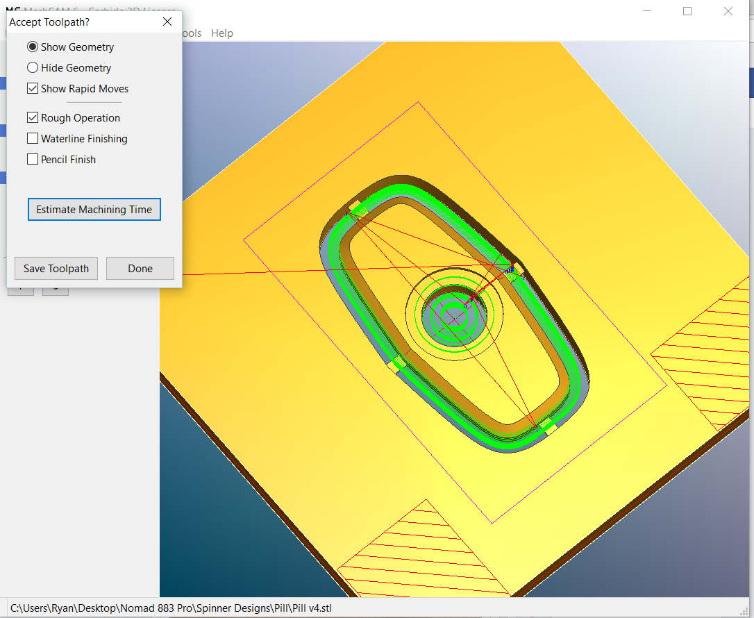
Is there a way to prevent Meshcam from roughing this hole what seems like repetitively to me?
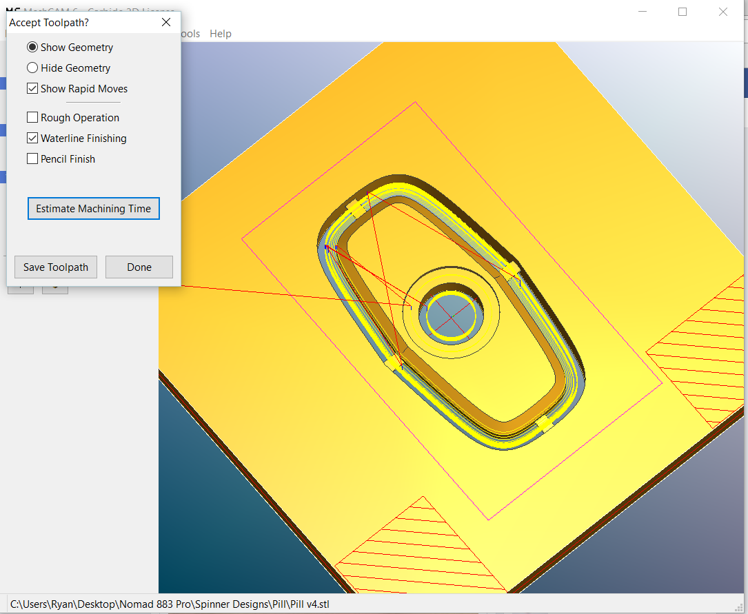
Also, could this design be done without a roughing pass and just using a waterline?
Is there a way to prevent Meshcam from roughing this hole what seems like repetitively to me?
Also, could this design be done without a roughing pass and just using a waterline?
You can try reducing the machining margin, that should reduce the number of passes around on each roughing pass. If you create a “do not machine” region in the middle of the central hole (but leave at least some space around it for a cut path, you’re going to need to fuss with it a little) you can get meshcam to not try and do that second inner roughing circle in your middle hole. Meshcam thinks it nears to clear that whole hole out, which is why you get the second/third cycle in there.
I suggest using Carbide Create for the Holes.
Keep a Common Center Zero location and you can experiment with the bearing fit:
So you’re saying essentially to design the geometry in CAD without a hole, run that job, then design the through hole in Carbide Create with the same stock and run that job to mill the hole?
It seems like Meshcam could be a little intelligent here I guess, but I like the workaround idea.
Not really. You don’t need to mill out the whole hole for it to be a hole - you just need to get the outside. Meshcam thinks it’s a pocket, so it’s clearing the whole thing. It’s not doing anything wrong, it’s just taking longer than you would like…that’s just a way to…“convince it” to do what you want.
I guess the programmer in me thinks Meshcam should say, “hey this pocket is the depth of the defined stock, no reason to mill out the entire stock, just the perimeter.” Or, at least present the option.
At any rate, the way to get around this is to just add a center to the hole offset by .15" or just larger than the tool diameter. Additionally, a machining margin of just over the tool radius seems to pull the wool over Meshcam’s eyes in this design.
Not going to disagree…
No need to modify the 3D model to get rid of the hole when setting up the file. Just use the “Cap Holes” command in MechCam
Ryan, don’t model the stock and supports as it appears you have done. Just define and lock the stock dimensions, and place the geometry in the stock boundary the way you want it. The way I’d go is as mikep said–make the machining margin about 60% of your cutter size and it will leave just a little kerf around the edges. This will reduce any extra machining around the perimeter of the part too and minimize the support/tab length.