Just thought I would share in case someone is worried about how level their wasteboard is, or wondering how important it is to face the wasteboard to get it level. My machine is an XL.
What I did:
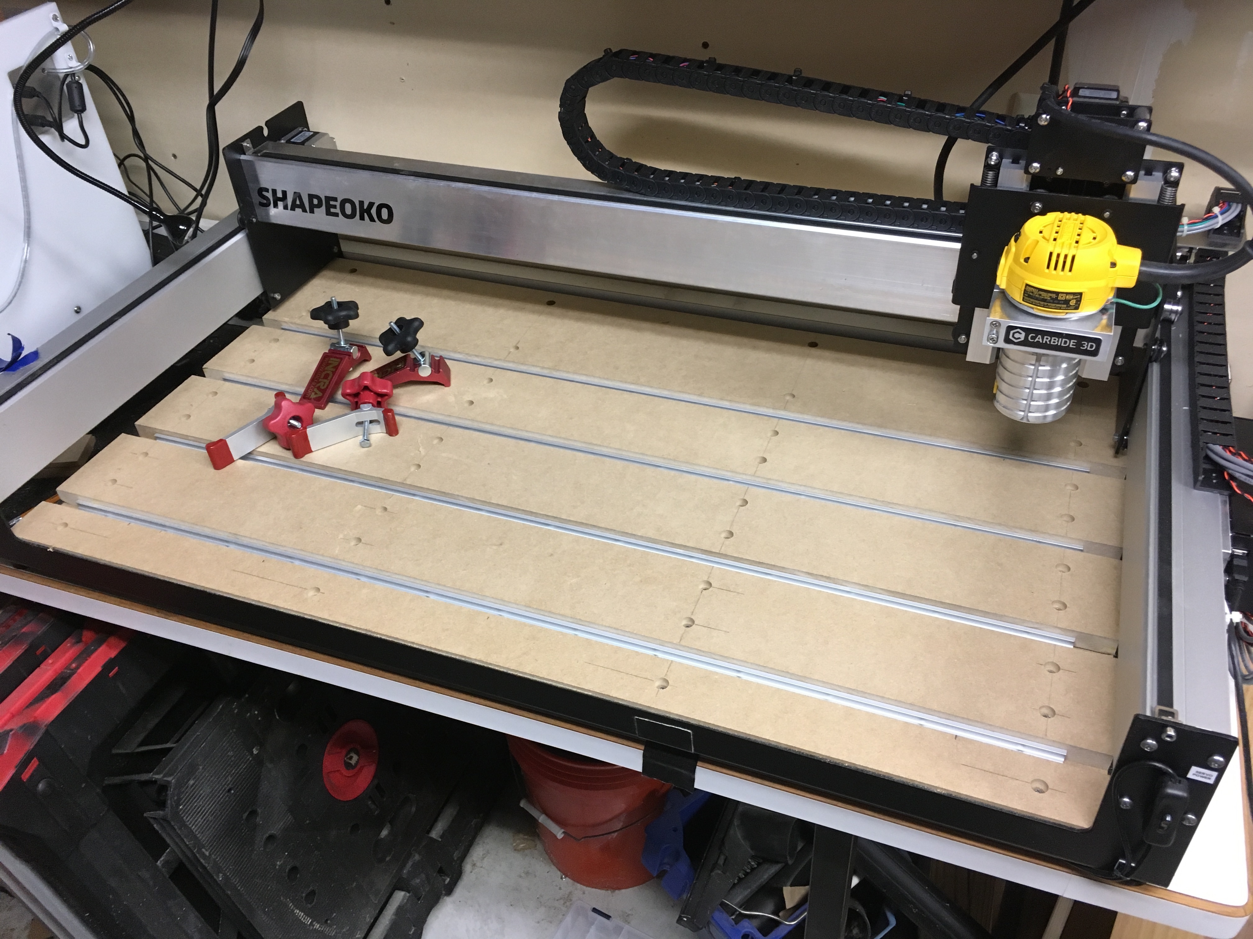
Mounted a dial indicator on a dial indicator holder. Removed the router from the Z plate, mag mounted the holder though the spindle mount, and put the tip of the indicator roughly where the end-mill would be. Exact placement isn’t critical. I started up Carbide Motion, and jogged to the front center, and called that zero. Then I just walked the spindle around to each of the other 8 “quick position” points on the table. The indicator was on the table directly, not on the tape you see here.
I did spend some time cleaning the powder coat out of the axis mounting holes, loosening and tightening with pressure applied to make this better…but that’s only good for about .010" or so. The deltas after that work are shown in the photo.
The stock wasteboard isn’t super rigid - it’s just fine, just expect it to move 5-10 thousandths with a couple pounds in the middle of it. The edges move less, the middle most. That does mean that if you’re within about .010", it’s not going to be repetitively better than that (unless of course, you build a torsion box or something like that instead)
So, with a basic build, there’s about .030" between the back left and the front right corner on my machine. Maybe I’ll spend some more time with it, maybe I won’t. I’ll be putting another 1/2" layer on top of this with some t-track, and then I’ll face that to take out whatever is left.
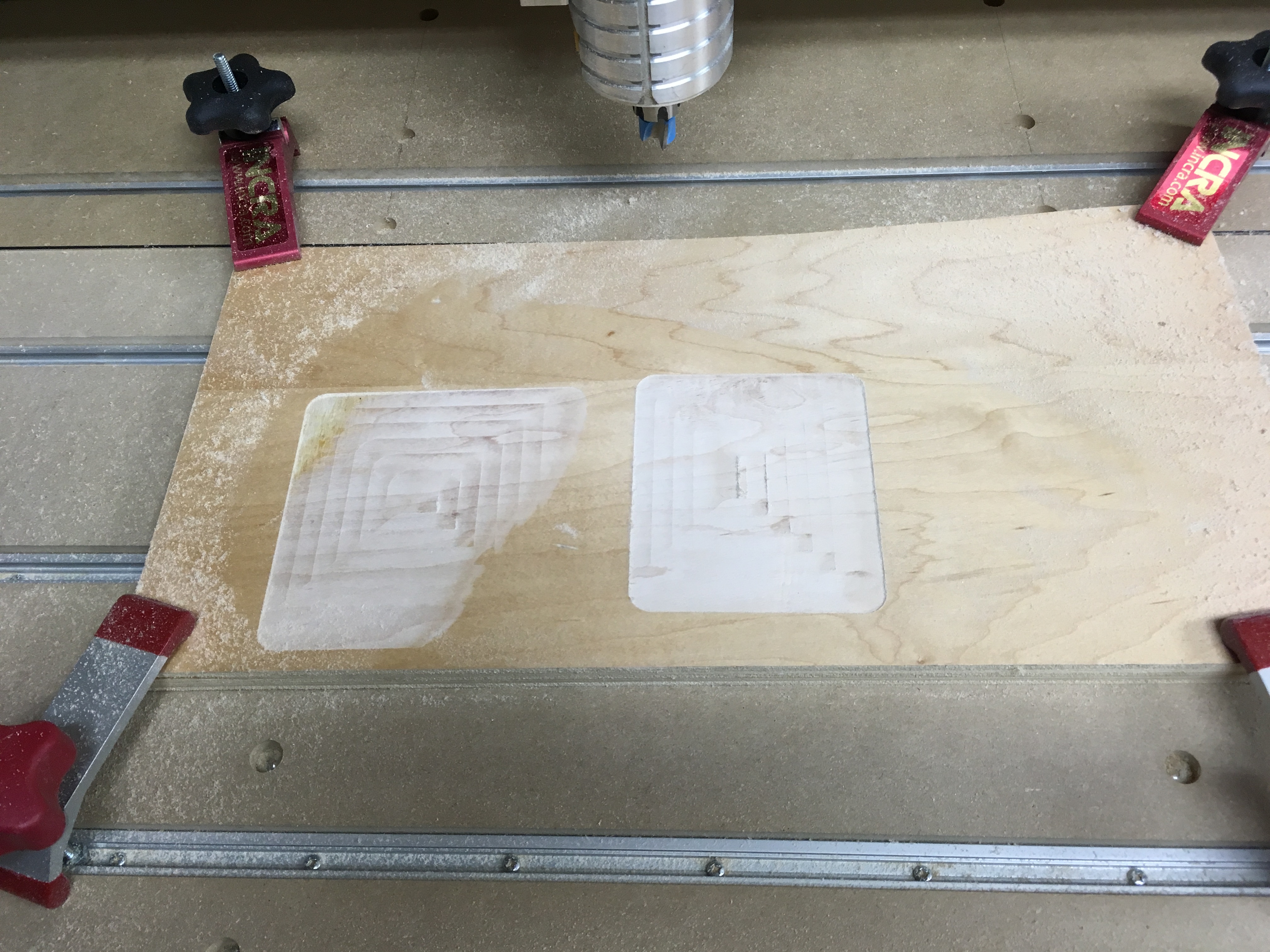
Here’s a little perspective. Cut on the left was .010", zero at the front left before surfacing the wasteboard. Cut on the right is .010", zero at the front left after surfacing the wasteboard. There is a black line around the surfaced area, makes it look a lot deeper than it really is (yes, the board is completely inside the surfaced area even if it doesn’t look like it here )
The Incra’s are from the build-it system like Will says, the “plain red ones” came with a Woodpecker’s drill press table. Either variety costs about $10 give or take. The back track is far enough back that the spindle can’t hit the knobs.
The t-track is “Orange” brand, and has clearance in the bottom for screws to mount it. Used 48" lengths cut down.
Plenty of makers of the generic looking clamp, like this all in that $10 range (with shipping):
Here’s the carbide create file for surfacing an XL with a 3/4" bottom cutting router bit, zero at the top left corner, taking off .050" You’ll need to change it for where your high point is (where you should set zero), what tool you have, and how much you want to take off. The way I did this, you’ll want to set the DOC for the tool to the depth you want to take off. I strongly recommend you do an “air cut” above the surface first just to be sure it’s doing what you think it should, not bumping into limits, etc. Remember, MDF is awful stuff to cut and kicks up quite a mess of gunk you don’t want to be breathing, so wear a mask.
Yes, one of the straight bits should be fine (in general, router bits with appropriate paths, feeds, speeds, and depth of cut, are fine so long as they don’t have bearings) — just take a really light pass / skim cut so that you don’t overtax the machine or cause things to not be plumb and square.
Cut them in mirrored pairs, pocket the inset half the diameter of a #10-24 or M5 bolt and assemble w/ #8-32 or M3 hardware. Cut a 3/4" dowel to length and drill a hole in it for the selected hardware.

 )
)