Hi all! This question is mostly about SuperPID, but I know a bunch of you use these, so I’ll start here and see if anyone has suggestions before heading to SuperPID forums (if there are SuperPID forums, I’m not sure.)
I’m installing a SuperPID on my Shapeoko 3, along with a small control box with toggle switches for powering on my dust control, router power, Shapeoko power, etc. I’m also going to wire the SuperPID so grbl can control the run state and RPM of the router.
As I see it, there are three places where I could put a router power switch:
Interrupting the “Run” wire from the Shapeoko board, so if the switch is off, regardless of what grbl is asking for, the router won’t spin up.
Interrupting the input mains voltage to the SuperPID. I know that SuperPID detects mains, so I’m not 100% sure what will happen if SuperPID is on and mains are off; if it will gracefully recover and transition when mains are flipped on.
Interrupting the mains output from SuperPID to my router. I’m not sure how SuperPID would react to this when 0 RPM is detected as current is enabled, but I figure the worst it could do is ramp up to 100% mains voltage / current. I don’t think I could flip the switch on at that point or it might damage the router not soft-starting.
I also have a master emergency kill mushroom button that kills power to everything, so the above is more as a fail safe when working on the router with the rest of the system on (tool changes), so I can’t accidentally bump a key on my keyboard and have the router spin up while I’m still doing something.
It seems to me that perhaps #2 is best, if SuperPID is smart enough to know what is going on. That would be the only solution where SuperPID could detect that I’ve cut power. In #1, it could be receiving RPM PWM signals without a corresponding Run signal… I’m not sure how it would handle that.
Any thoughts? How did others with toggle switches and SuperPIDs wire theirs?
Unfortunately I don’t run my SuperPID off of the board, I used a switch and a knob so I can’t exactly advise. However my thoughts on an “Emergency Kill” switch is that it should cut power to the mains and SO3 and effectively “Kill” all possible movement… If it’s a true emergency you want it to stop and you’re not so worried about recovery. It took me a while to get my head around this too, but with some suggestions from others I finally realized it’s the right thing to do.
Nice, thanks! Your build looks similar to mine, but yours is nicer!
What are the two toggle switches on the top of the box?
I do have an emergency button that kills everything, but since grbl has the ability to spin up the router, I want a manual override that leaves grbl on, but the router off, so if a feed hold is accidentally continued while I have my hands in there, the router doesn’t start on me.
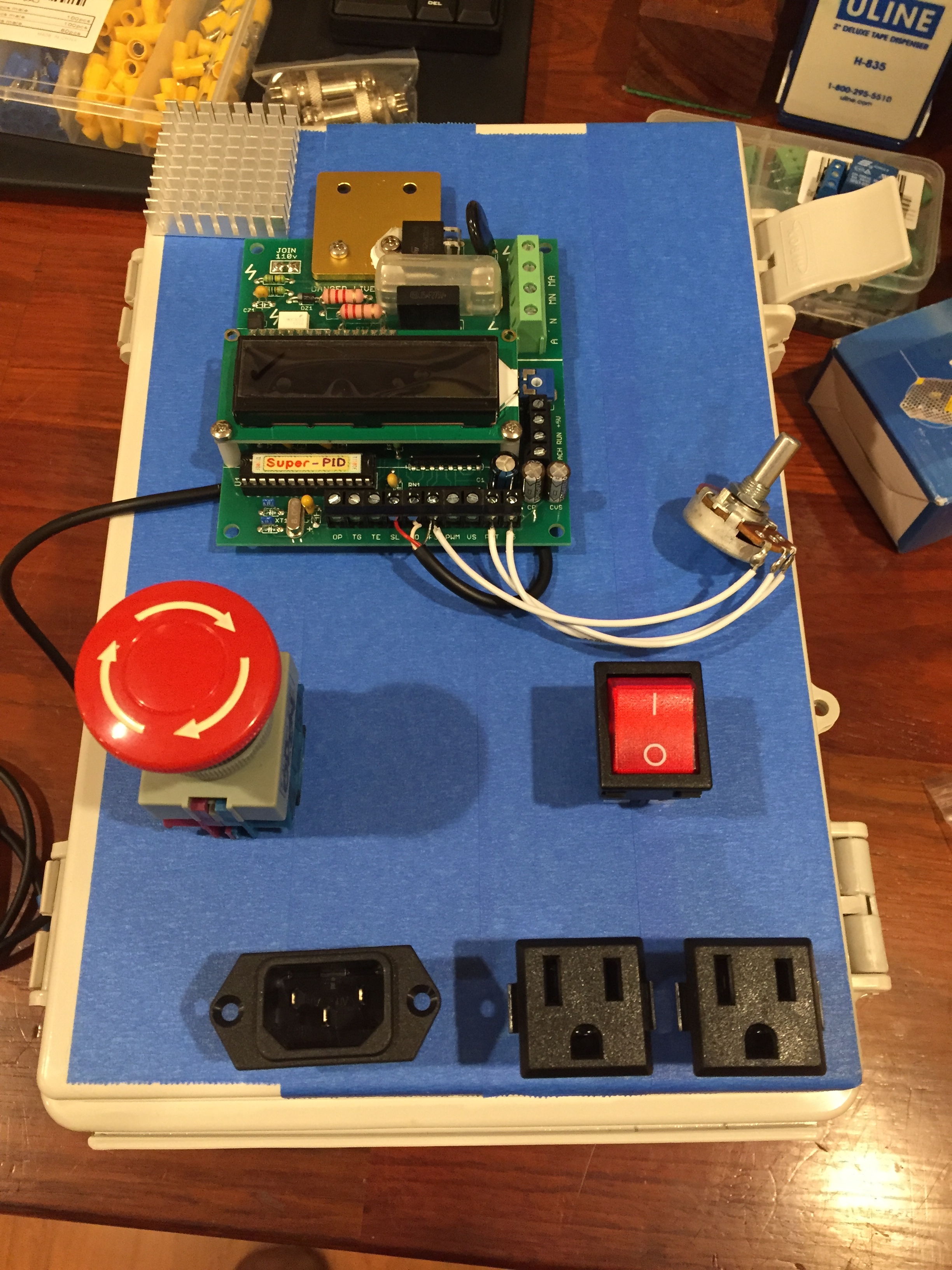
I have two switches to the right of the knob, one supplies 5V to the SuperPID board and the other toggles run/stop mode. The knob is RPMs obviously, on the right I have the mushroom kill switch, above that is ShapeOKO power and then router power. I broke the tabs between the two outlets so I have two distinct circuits, both die when I hit the Emergency Stop.
Yea, I wanted the same initially, but cutting power completely during a real “stuff hits the fan” emergency seemed safer. I don’t want to rely on a piece of code or an arduino board with my hands in there. I try to remember that everything fails eventually, and after all, these are hobby grade machines (albeit really nice ones), but still hobby grade and even the “real” machines fail unexpectedly. I forget who mentioned all of this to me back when I was doing mine, but it stuck. Honestly I’ve yet to have a fail that I could have recovered from if I had just “paused” everything, so in my mind at least I took a good approach.
Looking forward to seeing what you come up with in the way of an enclosure, etc… I’ve seen some really cool looking control boards here on the forums that make mine look like a bunch of junk.
Exactly! I’m right there with you! I have an emergency stop mushroom button that cuts power to everything.
Ahh, ok, so you have implemented what I listed as option #1 (using the Run wire). The only difference is my switch will interrupt the signal from the Motion board, so in order for the router to start, the toggle switch needs to be on, AND Motion has to send the Run signal.
Perhaps I could implement a DPDT switch to interrupt the PWM signal wire as well, so when my router switch is “off”, the SuperPID does not receive either the Run signal, or the PWM signal from the Motion board.
Thanks, brainstorming and reviewing what you have implemented was helpful!
I added the SuperPID to my SO3, and set it up to be selectable between being manually controlled and GRBL controlled. My build log is here. I did this over a year ago, so the details are a bit fuzzy, but hopefully I captured enough detail in my BLOG to give you some ideas.
Note that I have one of the early SO3’s where it would lose USB connectivity for “unknown” reasons. I did get a replacement Carbide Motion board (with the HUGE capacitor hack), but I never really got the GRBL control aspect to work consistently. I have just been controlling it with the switches and POT, which has worked out just fine.
I just found some time to read through your post. Thank you for sharing, this is exactly what I want to do, and your notes are very helpful!
I have a few questions:
When you flip your Router Power switch to On, if Speed Control is set to PC but the Motion board is not sending a PWM signal, what speed does the router run?
Regarding the K-mode vs. linear mode… Did you de-solder the pads on the back of the SuperPID and connect them to your manual / auto switch (must use a DPDT switch?) Does changing the RPM response curve while the SuperPID is running work properly? I assumed (with no data at all) that they made this a solder jumper rather than a normal jumper or switch because it wouldn’t work properly to change the response curve while the board was running. I’d love to hear that re-wiring it works perfectly!
Does a lack of soft-start result in a relatively harsh start when in manual mode, or is it fine? I’ve heard reports of no soft start being bad for the router when going to high RPMs, but it doesn’t make sense to me from a mechanical standpoint (why starting up at 100% would be bad). Or do you always turn your dial down to minimum and then ramp it up when starting in manual mode?
If you were going to do this again, would you change anything?
After both you and @DanoInTx said you use the Run wire to control router power, I’ll definitely do that. After seeing your setup, now I’m probably going to implement two switches the way you did, to separately control PC / manual control, and Router off/on.
I have never tried this, so I can only assume what will happen. I think I remember reading in the Super-PID manual that the slowest the system can drive the router is 5000 RPM. Based on that, I would figure that a flat-line PWM input from the computer would result in driving the router at 5000RPM.
Yes, I de-soldered the pads on the back to connect it, and the RPM input, to the same switch. This way, when the switch is in PC mode, it is in linear mode AND the speed input is connected to the PWM signal; when it is in manual mode, the Super-PID is in K-mode and the speed input is connected to the POT. I have not tried to switch the control mode in the middle of a Super-PID power session. If I know I am going to run a job manually, I have all the switches set correctly, and the SO3 is powered on, before I turn on the Super-PID (using my wall switch). You will have to ask the Super-PID makers if they read the mode switch real-time or just on power up.
Actually, the Super-PID appears to have it’s own soft start feature. If I have the POT set to 18000 RPM, the router gets up to speed in 2 audible steps. I haven’t paid attention to what the initial speed is, but on startup, it reaches that initial speed in ~1-2 seconds, before it is ramped up to the set speed.
In all honesty, I haven’t really used the full capability of the Super-PID yet. My SO3 spent almost its entire first year taken apart, as I added one upgrade after another. I am just now getting into cutting wood; I hope to get into plexiglass and aluminum later. I would expect to use the Super-PID features more then, and I would expect to have a “wish I would have done differently” list then as well.
Please report back here when you are done. I’d love to hear how you fared and what you like/dislike.
I emailed SuperPID regarding adding a switch to change between linear and K mode RPM setting and received the following response:
For the level that you are referring, generally not needed or recommended. You would need a separate switch, and yes will need to kill the power to do this level of software/firmware resetting. For this level of super-nerdiness you will always need to remember to power-down first and not accidentally switch it when all is powered up. Could be risky (and really not needed) for most of us mere mortals…
So it sounds like it works, is unsupported, and a power cycle is necessary… basically everything we assumed, but now officially.
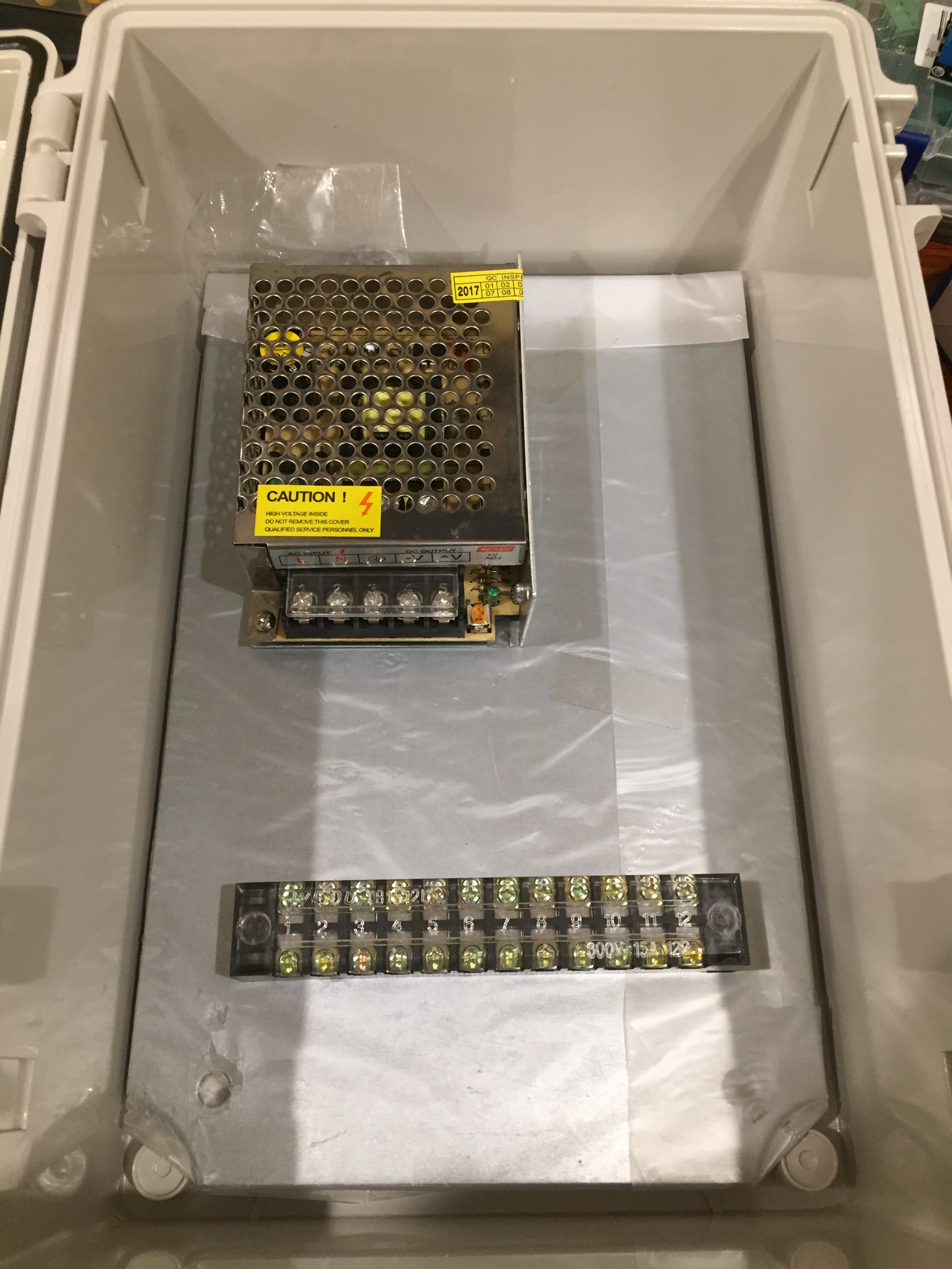
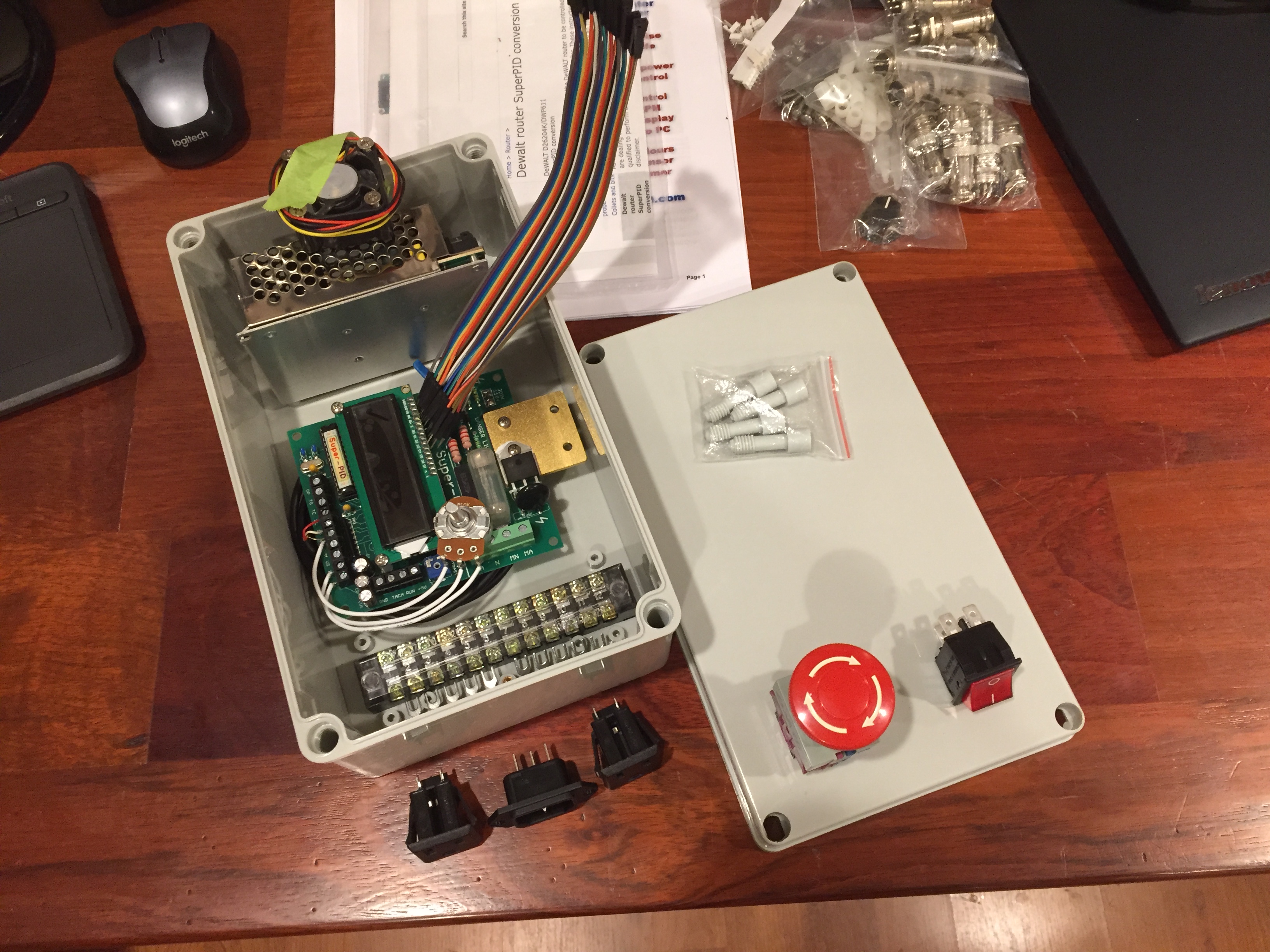
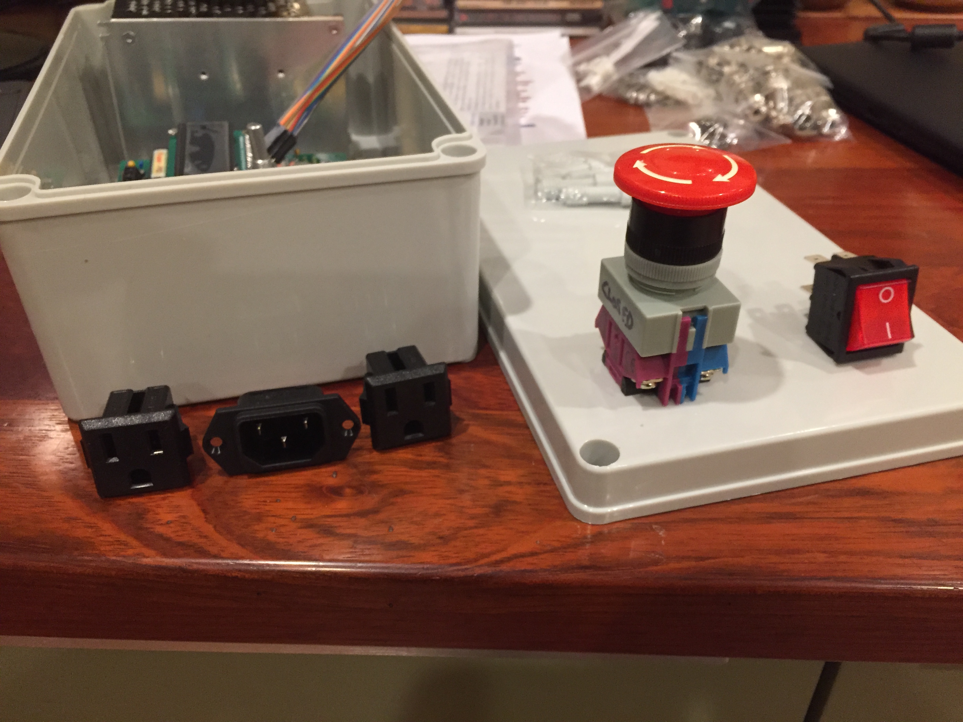
I’ve assembled a bunch of components to wire up the Super PID this weekend while also installing a new SO board v2.4. I believe this board is supposed to eliminate most/all the EMI issues the order boards had. I have a large sealed project box to install the S-PID into along with a terminal block, switches and a 5V power supply.
In the box I was planning to run the 110V line in first to a stop switch, then a rocker, then the terminal block and from there split it (1) to the line in on the S-PID (2) the 5V supply and (3) out to power the SO controller. The line out from the S-PID will exit the box near the line out for the controller. The goal is to be able to hit the kill switch and stop the router and controller together.
I am also adding drag chain to X/Y. The cleanest setup will be to run both the router power and the SO control board power both thru the drag chain.
Here’s my question: will I continue to get the EMI disconnects if I run the router and controller power out of this box and then thru the drag chain paralleling each other? I plan to keep the cable from the computer to the controller out of the drag chain altogether.
I have a very similar setup, including the power configuration you have described, drag chains, a 2.4d board, and my mains voltage router wires running in the same drag chain as the RUN and PWM signal lines, and the usb cable.
I’ve never had a disconnect, ever. I never had one of the older boards, so I never had an EMI problem with my S3, but I do have another CNC mill with a generic board that suffered from the end-stops triggering from EMI until I added some capacitors to the lines.
I think the 2.4 boards are just better, and you should be fine running everything in one drag chain, but perhaps I just got lucky somehow and my experience isn’t representative.
For the 5V power I just use a simple USB cable and pull 5V from that. You can use something as simple as a cellphone charger for power, no real power supply needed.
Understood but I felt it was cleaner to have the 5v supply in the box. I’ve got a tub of old wall warts I just wanted to power everything from one plug.
I c, coolness! I partly opted for the USB because my enclosure is mounted to my bench right above my UPS which has two USB ports right on the front. I took an old USB cord, cut one end off and soldered on a 2 conductor plug, mounted the female side of the plug on the bottom of my SuperPID enclosure. Only problem I have is that on occasion I unplug it to charge my phone, I’ll get all ready to run, turn on SuperPID and it doesn’t turn on. Leaves me head scratching for about 30 seconds every time, duh me! I think you’re going to really like the SuperPID, it’s a great piece of kit.
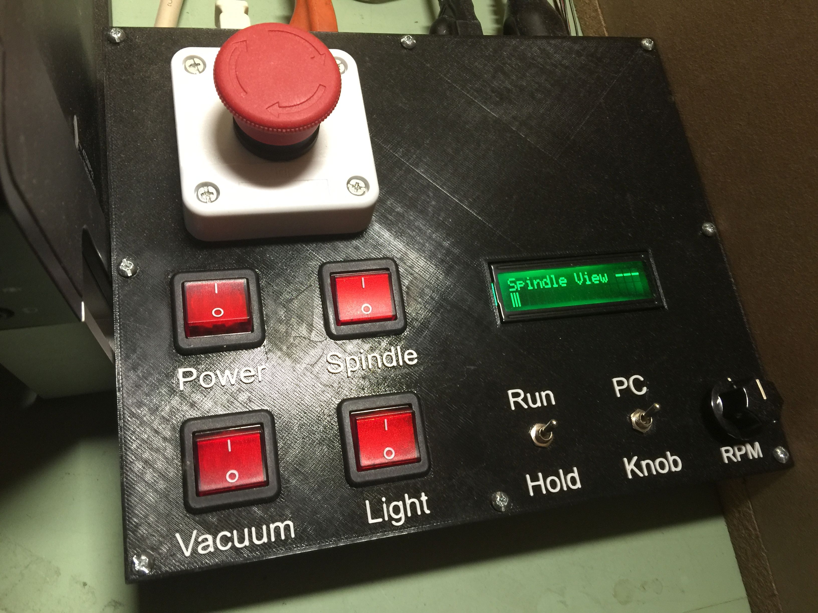
I did something in between what you guys (@rmwarren and @DanoInTx) discussed above… I used an old iPhone charger (the tiny one), and wired up a USB charger inside my control box. I soldered wires to the 120v ends, then covered them in heat shrink tubing to protect the connections.
I 3D printed a control box (with a filament color change, so the labels are printed as well), here’s what it looks like: