Unfinished first project on the Nomad, need guidance

Hello All,

This is my first post here and I apologize if this is not the right channel to ask for help. I’m just lost with all the information (or lack thereof) about MeshCAM and the Nomad.

In my first project I want to mill two rollers on hard wood and I think the geometry is much simpler than others I’ve seen on demo videos. However the toolpath calculation takes too long and if I have the patience to let it finish, I see that the machining time is unrealistic (over 7000 minutes).

I have played with the settings and I have tried other STLs with equally simple geometries and I get the same issues: too long calculation and machining times. I created the STLs myself with TurboCAD. I’m wondering if I can get some pointers here, if I can upload the STL for review, etc. I’m hoping that with the help in this forum I will be able to use my unpacked Nomad for the first time.

Thanks for your attention,

Ric

@Cereza

The STL would be great and some dimensions.
Can you post a screenshot or sketch?

I can help.

Thank you Apollo,

This is a screenshot of my design:

More background: I am using metric by default, I want to do double sided machining, I generated the toolpath with the Carbide Auto Toolpath option and accepted the defaults offered. I selected the #102 for roughing and the #101 for finishing. The stock is 120x80x80 mm.
Here is the STL: Two.Rollers.for.Abs.Machine.2.STL (2.0 MB)

Thanks again,

Ric

I think your Z hieght of 80mm ("3.15) is a problem, and you may want to consider a different approach.
If you split the wheels up into 2 halves, you can take advantage of a Waterline toolpath and you may not need to flip your parts at all.
I made an example, see below.


The Sheet Material required for this approach may also be easier to source and would less expensive.

I am aware that this is not the optimal way to make the rollers. In fact, this is a project for a lathe (that I don’t have). I can’t split the rollers in half due to the forces they will be submitted to. But your solution shows how a turning problem can be made into a milling problem, thanks for that.

From your reply I would think that my issue is that I am exceeding the 8x8x3 limits of the Nomad. But even if I scale the project so that it is well within those limits, the problem is the same: MeshCAM is taking too long to generate the toolpath.

A look at the Toolpath Generation page shows what I think is the problem: the stepovers are too close and the step down is too shallow.

This is my workflow. I apologize if it is too long, but you might find my mistake here:
I open the STL and choose 2-side machining.
I translate the geometry so that the XY center is zero and the top is zero. I expect that my (0,0,0) is right on the middle of the top face.
I don’t add supports, don’t change the cutting depth, don’t set a machining region and don’t put supports.
I set the Program zero to be on the top face and the middle of the top face.
I drag the drawing with the mouse from bottom to top of the screen and I see a green line, a blue line and a red line at the bottom. I think that is the 3D origin which I don’t expect it to be there.
I use the Carbide Auto Toolpath from the Tools menu (which I discovered on one of the many videos I could find about MeshCAM), change to Hard Wood and turn on the Review Toolpath button.
I see the toolpath parameters window and I click on Use MM since that’s the only thing I know, inches don’t make sense to me.

As you see, the stepovers and stepdown are too small. I don’t know why and I think that’s where my problem is. Anytime I was offered to use MM I used that option.

I uninstalled and reinstalled the program, but it seems to remember my old settings. I didn’t even have to reenter the activation code again.

If it helps anything, I’m running MeshCAM on a virtual machine, but on videos I’ve found this doesn’t seem to be a problem.

Again, thanks for your help.

@Cereza
To reduce the run time on your part I used some of the MeshCAM options and then adjusted the Toolpath settings for maximum effieciency, however I do always recommend a test cut in scrap material if possible.

  1. I scaled the part in meshCAM to get it under the 3" Z limit.
    The Scale factor was .9

  2. I used a keep out area to limit the machining area and run time.

  3. The Tool Path is set to machine “Geometry Only” to reduce machine time as well.

( I think in Standard when setting up toolpaths, but you can toggle the units to MM if you prefer)

Heres the MeshCAM file for your reference.
two Rollers.mcf (1.9 MB)

Heres the Tool Path Settings file for you to load.
hdpe 3d 125 ball.tps (2.1 KB)

I set this up for HDPE and got the machine time to 1.5 hour per side.
No tool change required, the .125 ball is used for the roughing and the finish pass.

(For your final part in ABS you may need to reduce the DOC of the Roughing pass from .030" to .015")

Run Time Estimate

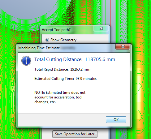
The Roughing pass is the majority of the job due to the orientation of the parts.

Note the orientation of the Parralel pass, and absence of a waterline pass due to the orientation.

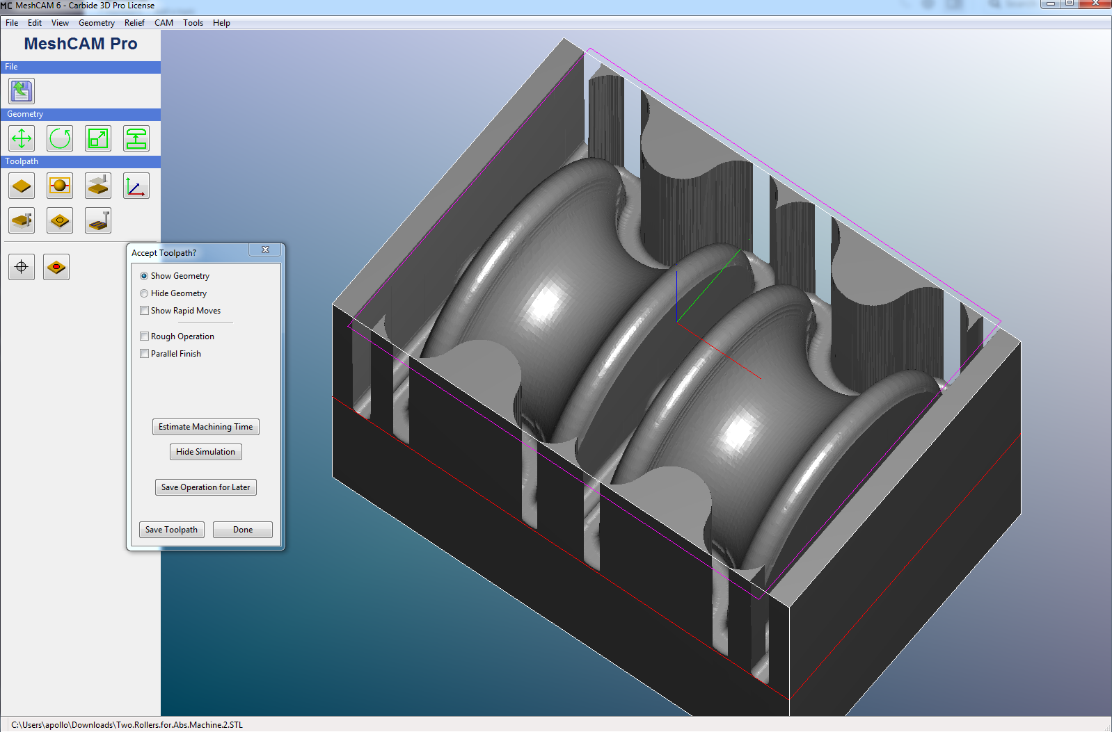
“Geometry Only” will only reveal the parts, and save run time.
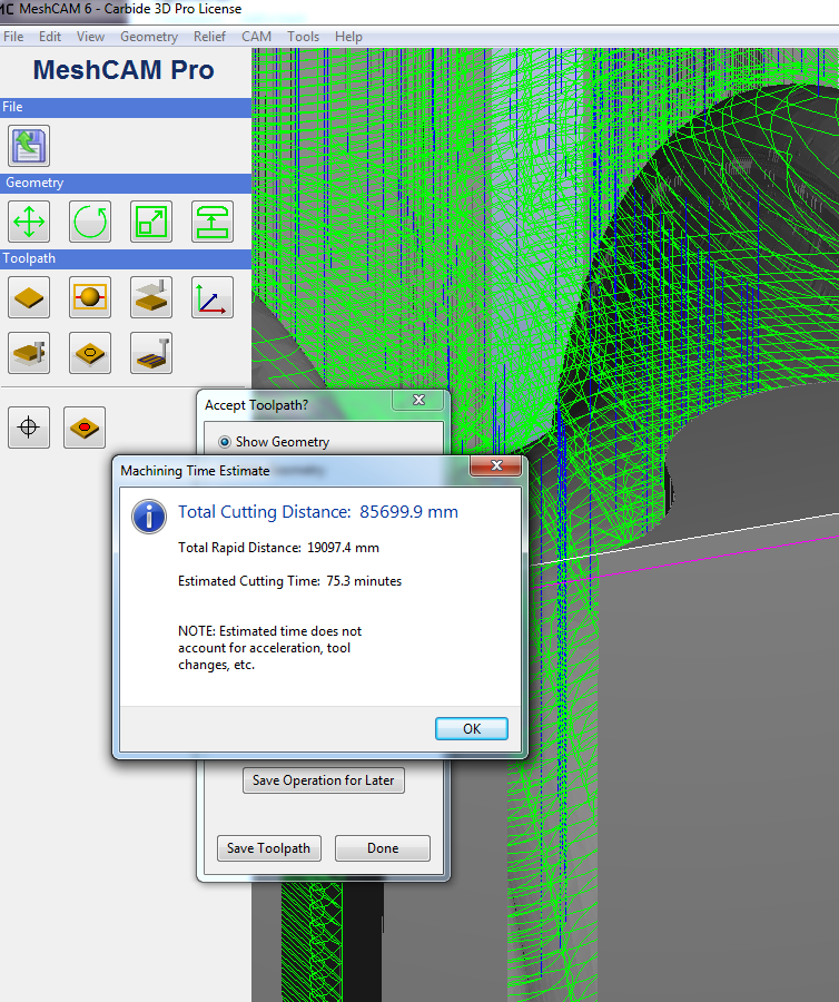
Toolpath View


The Purple rectangle is a “Keep-out” area, This may be able to be further adjusted to save run time.
Currently it is allowing meshCAM to read the walls adjacent to the wheels, which is extra run time.

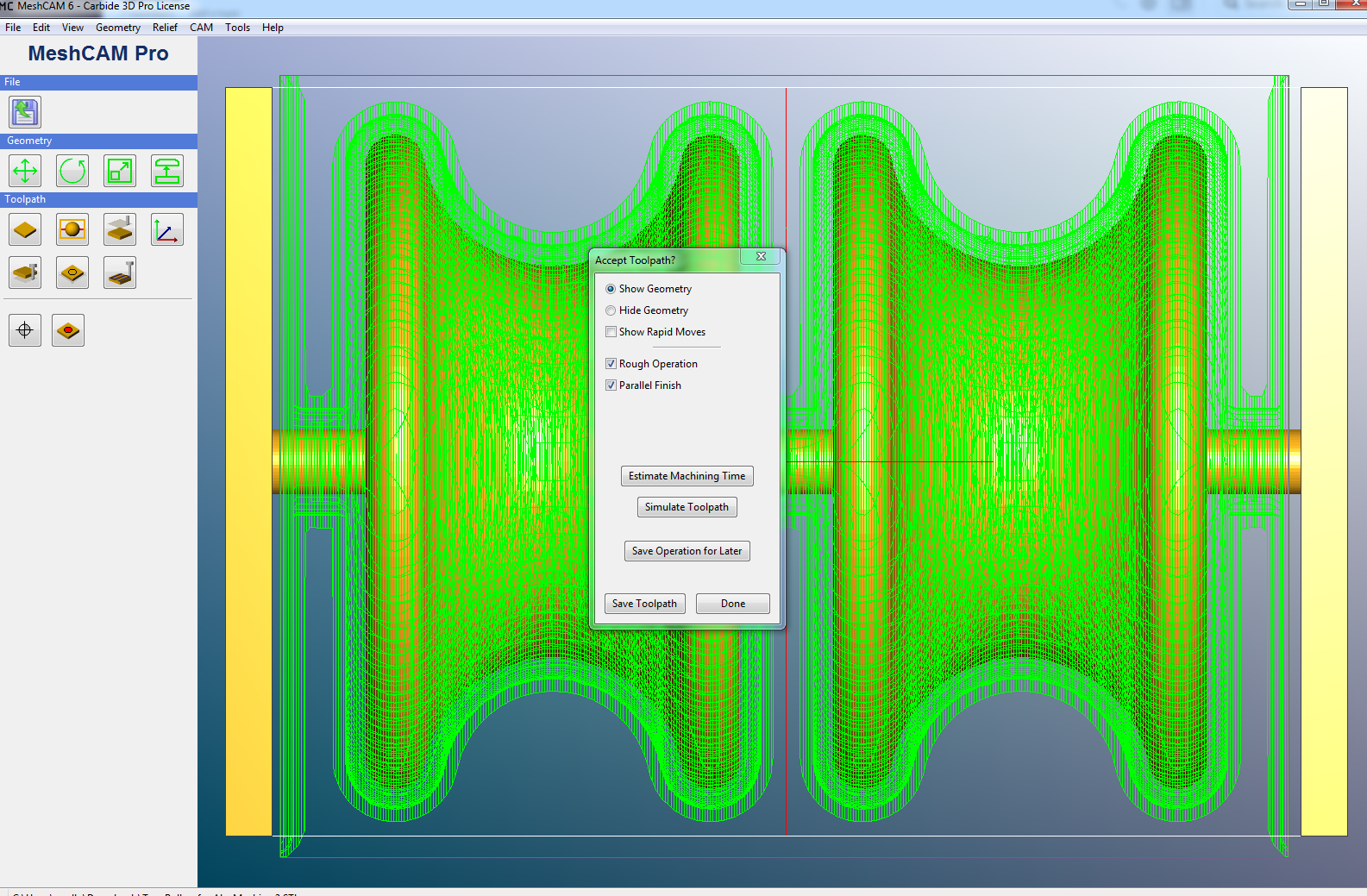
Parralel Finish pass


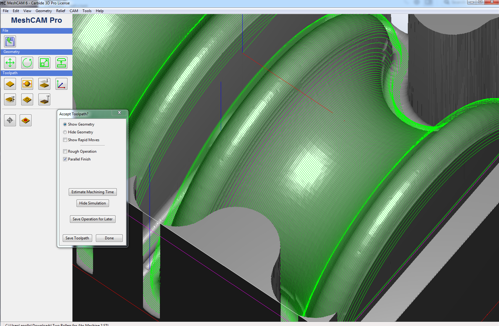
Here you can see the Finish pass is oriented in the Y axis direction to respect the wheel radius geometry.

-A

2 Likes

I think we are getting closer… on my VM it took 6 minutes to calculate the toolpath with your settings. However, I still have some questions:

  1. You say to note the orientation of the parallel pass, however “User Parallel path” is not checked neither on your screenshot nor in your configuration file. Are these two different concepts?
  2. Your toolpath parameters are very different to those generated by Tools -> Carbide Auto Toolpath. I used HDPE (I will be using hard wood) and the #1 tool (the Nomad comes with a #101). I said “Yes” to copy the default parameters for the tool. How do you get the values of Stepover, Feed rate, Plunge Rate and Stepdown?
  3. When I loaded your file, I had to rotate the STL 180 degrees around X to have the coordinate origin on top, but then If I load my files, the coordinate origin is at the bottom. This is my fault, in my dispair I’ve tried every setting in the program. How can I correct that so that all files I load have the origin on the top? (Rotating and saving your file didn’t help).
  4. Is there a way to uninstall MeschCAM so that all configuration files and registry information are wiped and I can do a clean install? I uninstalled and reinstalled it, but my old settings were still there.

The parralel finish pass is indeed checked and the Y axis direction is also checked.
Are you looking at the screenshot I posted?
You will need to load the tps file after opening the MeshCAM file.
I set the meshCam file as a 3 axis job, this part is symmetrical so it’s the same exact job, you run it twice.
Post a picture of your stock and how your going to hold it.

I see “Enable finish pass” checked on your screenshot at the top, but “Use parallel path” disabled. Same thing in the tps that you sent me, which I know how to load. I don’t see anything with the word “Parallel” checked on the screenshot or on your file. I guess parallel refers to “Cut Along X” and we are talking about different things here.

At this point you’ve given me ideas on how to reduce the calculation and run time. Questions 2, 3, 4 about meshcam still remain to be answered, most importatly 2: how did you get the values?. Those values are crucial for the runtime. Should I open a new thread? Should I write to support at carbide3d as support at grzsoftware suggested?

As for the stock: after ten days of receiving it, I haven’t taken the Nomad out of the box yet. I want to sort out the software side before I start my first project.