I still haven’t found anything new to report. @LiamN, you mentioned that you have done a reduction pulley system, did it really improve anything? I am looking into doing something similar to gain resolution while dropping as much micro-stepping as possible.
1 Like
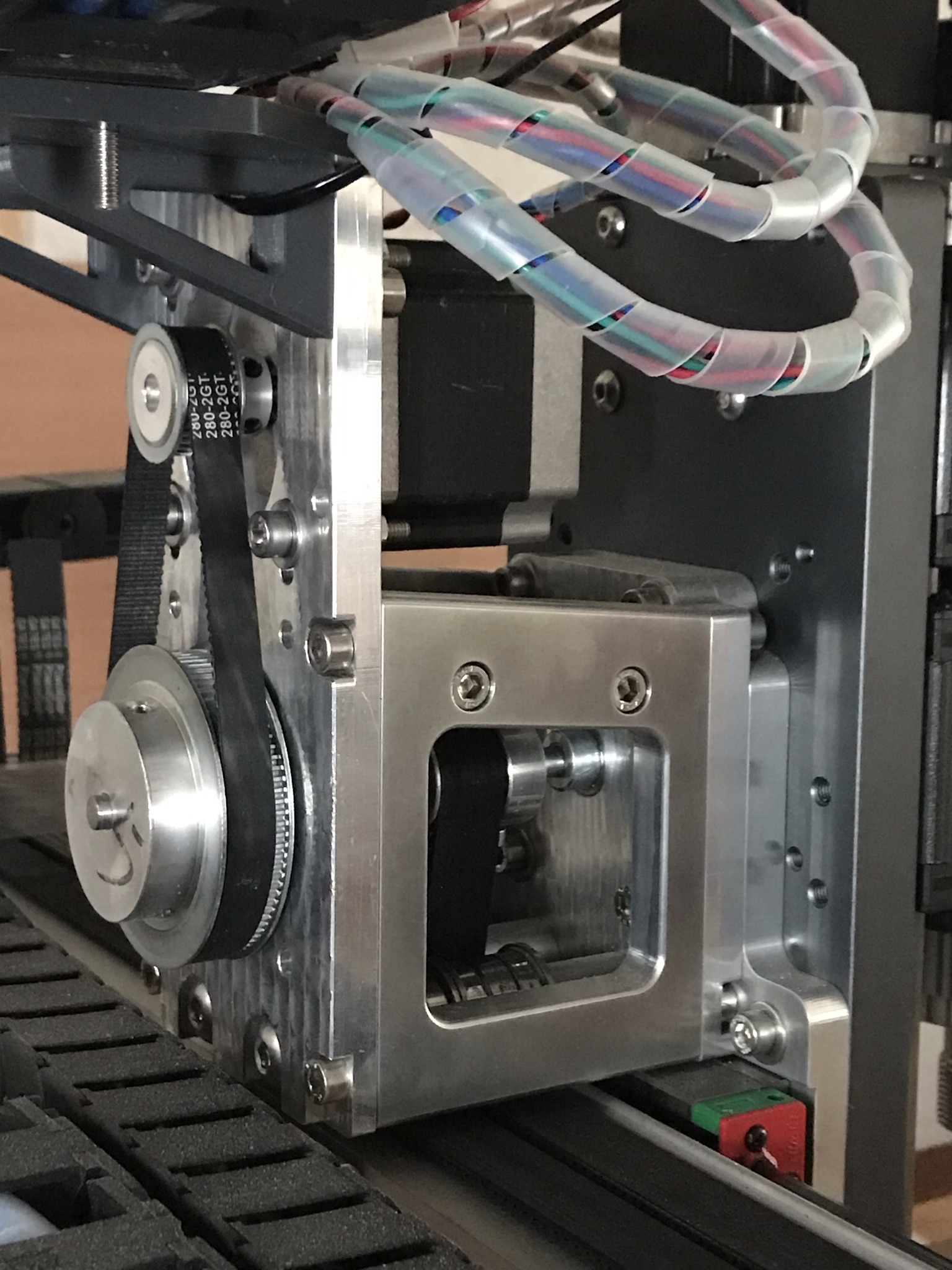
It seemed to improve the stepper deflection under loads applied along the X rail. I only did it initially because I wanted to use larger pulleys for the 3MGT belts.
Once it was assembled I found that the Hiwin linear rails had a lot more friction than the V wheels though and I was trying to reduce backlash so I geared down a little more.
I would not recommend this as a good trade off for effort vs. benefit, as an experiment it was a success, I learned things, I learned I wouldn’t do it again 
Trying to get extra resolution with the belt system is, IMHO, not a good use of your efforts, if you really want that, go linear rail and ballscrew and accept that you’re changing the motors, controllers and PSU at the same time.
I have less deflection now and can cut faster but I have no more precision than the machine when it was stock.
Yep, I get the same so far
I think I fell in this hole too. It’s the unsupported straight length of belt whose ends are the tangents to the pulleys that stretches, the teeth of the pulley hold the belt to the nominal pitch where it is wrapped on the pulley.
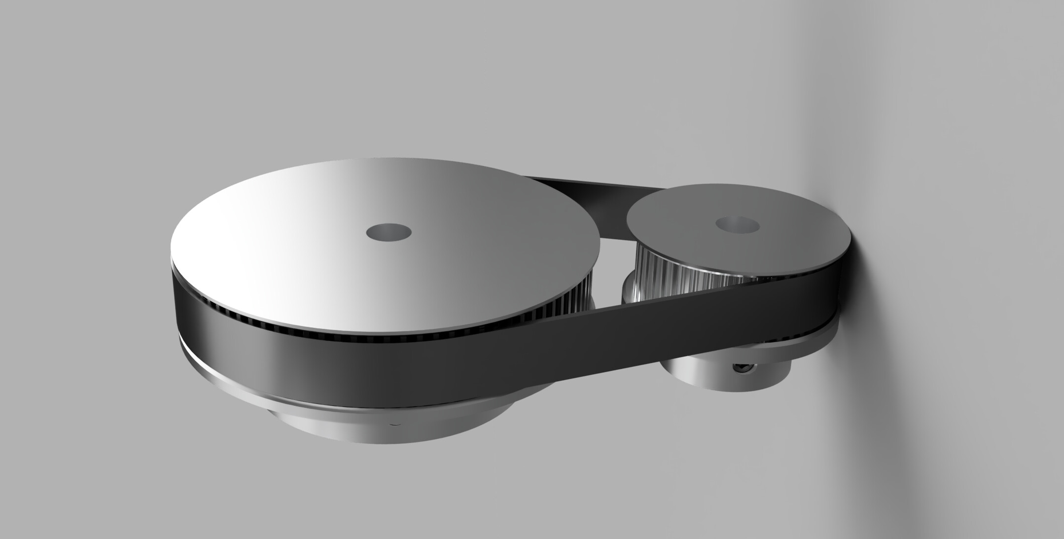
If anyone wants the Fusion models for the 2MGT and 3MGT pulleys let me know.
You have about 36mm (a bit less) on the 45T pulley (under 1/2 circumference) plus about 107mm on the 90T pulley. Drawing that out I get about a 240mm 120T belt of which about 48mm is unsupported between the pulleys on each side.
Then apply the 1.21% elongation to that 48mm section → 0.6mm
Carrying on with your numbers,
0.6 / 180 = 0.0032 rotation
0.0032 * 5mm pitch = 0.016mm
So ~16µm of peak stretch-induced deflection when your servos are loaded to their breakaway (or static stall?) torque during acceleration on the machine.
You could go to the 3MGT, they are certainly heavier duty belts, especially if you go to 15mm width.
Remember though that this is not your sole source of deflection in the machine, we are calculating the peak deflection under dynamic loads right at breakaway torque for your servos and you should not be doing anything remotely close to a finishing pass at those forces.
You are probably looking at 1/10th this force as a dynamic ceiling for a low-engagement finishing pass with sensible accelerations on the machine so you’re down to ~1.6µm just by disengaging Cleetus mode and not sending it.
I would be willing to start putting out the plate, cutlery and ketchup to assist me in eating my hat if the rest of your machine doesn’t have at least that deflection in it and we may well be below the accuracy of the ballscrews by this point too.
I have a roll of the Powge 15mm steel reinforced 2MGT here, but that’s open, not the closed loop. You can buy the 3MGT Gates belts, such as this one about the right length
https://buybearings.co.uk/product/gt3-165-3mgt-15-gates-powergrip-3m-pitch-15mm-wide
I got all the pulleys from Powge on AliExpress or eBay, they seem perfectly decent as well as cheap enough to modify on a lathe.
1 Like
Ok when’s the tutorial going to be published?!? haha
1 Like
Shhhhhhh!
I was hoping that Lucas would do all the hard work and then make a video…
![]()
2 Likes
I am really just trying to improve the surfaces on faces that aren’t parallel to X or Y. Right now there is a visible stair-step pattern even in very light finishing passes. I also wonder if the reduced torque at micro-steps is part of the issue. Hence my desire to do a pulley reduction since it is relatively low backlash and not very expensive compared to ballscrew. I won’t be going ballscrew on this machine. The cost and effort to change everything out and do it the right way is high. At that point I would rather save the money for a little longer and get a tormach 440 which is way more rigid and capable. I will be converting to linear rail relatively soon though.
4 Likes
Yep,
I have that issue too, curved faces on Aluminium have all the staircase on them. I’m not entirely sure if that’s controller or motor limits though. There was a long thread about wall finish and step size a little while ago that left me with more questions than answers.
Bear in mind that as you gear down the steppers you’re going to lose rapids speed on the machine, without more Volts the motors won’t go any faster so the trade off, in addition to all the work of belts for the steppers, is to lose speed to gain precision.
Thinking about it, if this were my goal, I’d start with replacing the steppers with 0.9 degree step motors (as Will suggested recently) to halve the step size. From there I’d replace the controller with a better microstepper which can cope with more PSU volts before trying to get enough step down in the belt transmission to make that difference.
1 Like
I started a new thread on this over here:
Switching the steppers is certainly a lot less effort than gearing down the existing stepper, not as much excuse to machine stuff though…
8 Likes
Don’t tempt me… I do really like how the whole idler/pulley/idler chain is supported on both ends.
1 Like
Well if you do decide to do something like that I’ll happily share the CAD as well as the somewhat irritating aspects of my design when it comes to assembly and operation so your 2.0 can be better.
2 Likes
I may have found the perfect project for when your Nomad upgrades are done
Now that is small scale accuracy
This topic was automatically closed after 30 days. New replies are no longer allowed.