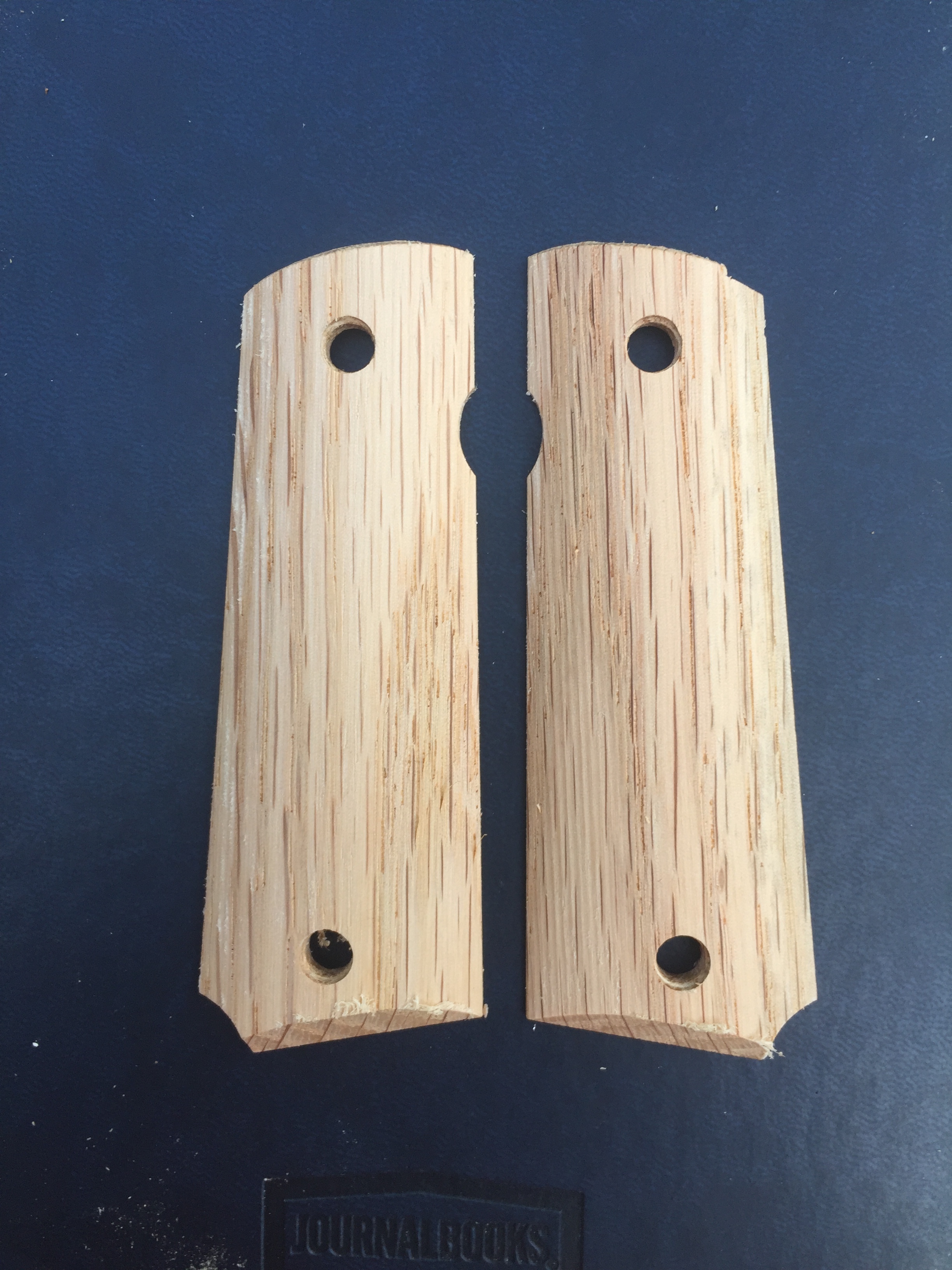
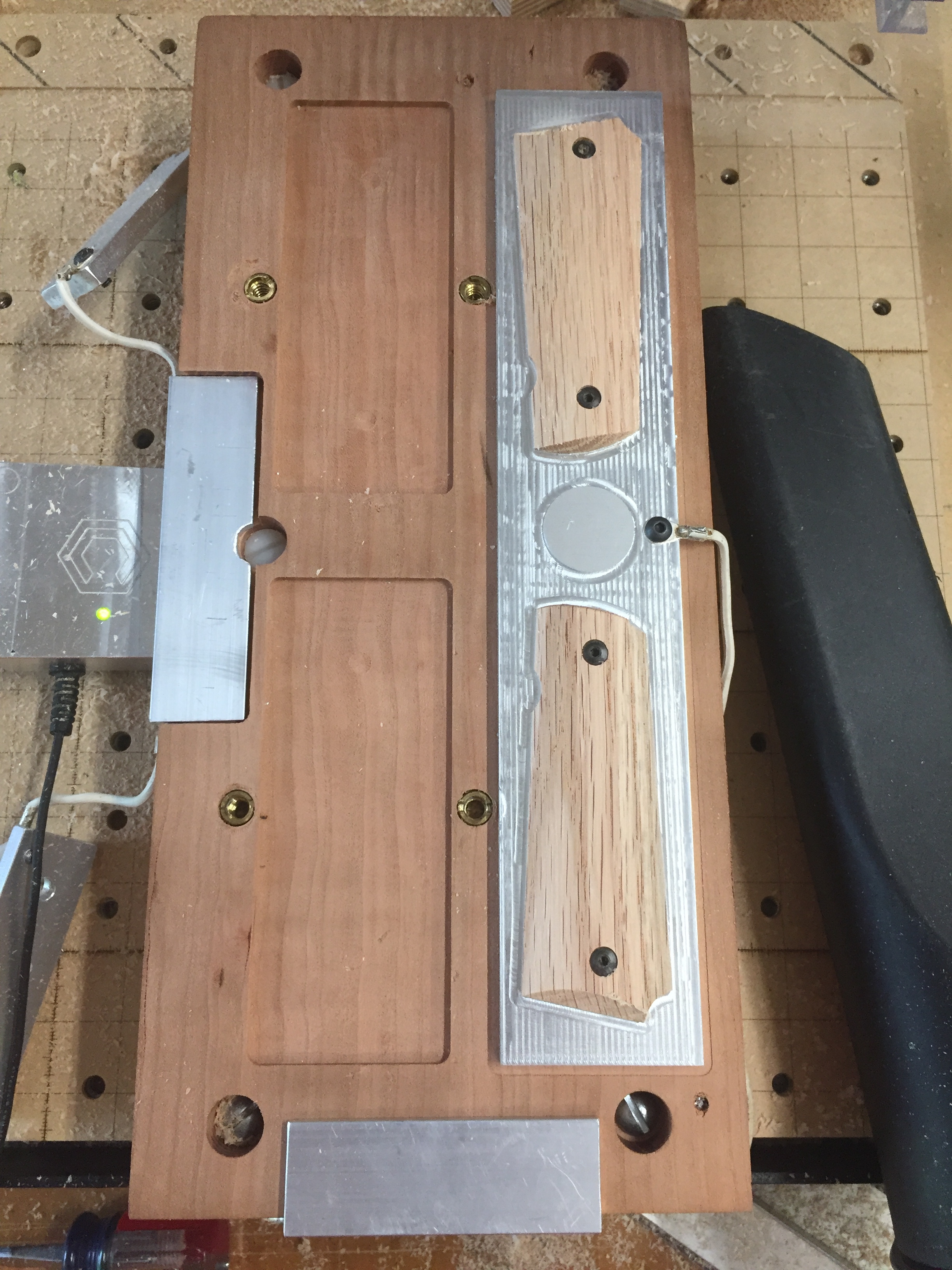
Made a jig to make 1911 pistol grips. I wanted to thank @wmoy for this Material Monday on cutting Aluminum on the Shapeoko because it really came in handy.
The STL file was created with Blender and the tool paths were created with Vcarve Pro. I still need to verify all the measurements and optimize the tool paths. If that checks out I make try to make some fancy ones.
You had me at 1911. It is amazing how John Browning designed such a machine over a hundred years ago and is still one of the best functioning designs in 2020. I have seen pistol grips a few times and would like to make some for my 1911 pistols. When you get your technique perfected please share it.
I have made a lot of turned pens and love any designs that have guns involved. I have used Walnut for quite a few of the gun themed pens and just love walnut. Walnut seems to complement the steel of a gun.
Machine top side of the blanks - XYZ Jig to Zero macro
Move to specific location with G53 G0 X-nnn Y-nnn Z-nnn which is above the Left piece of aluminum.
Pause to change bit, attach ground wire and probe to jig.
Automatically Probe Z0 from that location; move left a bit and Probe X0 off the left side of that piece of metal; then move down and right and probe Y0 off the piece of metal on the bottom of the fixture. Just like one HUGE touch probe.
The pockets on the left are milled to Z=0 so I just use “Machine Bed” tool paths to cut the top countersinks and thru-holes for the blanks. Makes it so blank thickness is variable and everything references off the back.
Machine the back side of the blanks
Flip the blank over
Because each blank may be different thickness I have the pieces of metal holding the blanks down wired to the touch probe. I can then run a “Surface” toolpath to touch off each blank and then cut the back side countersink. I do this to the each probe.
The cutout for the Plunger Rod on the left grip is cut at the same time as the countersink for that grip.
Finishing the Grips
Move the blank over to the aluminum block. It had to be metal as actual 1911 mounting studs are threaded into it. Being it’s metal it can be used to zero too. Install the blank and then screw it down. There is 1.5mm min between the cutters and top of the screws.
Run the cutout “Profile” toolpath to trim the blank to size. That also cuts the lower corner screw relief and the safety “divot”.
Insert a 1/4" ball nose and cut the 3D shape. I created my own STL file for this using Blender. 7% stopover and handle any sanding necessary and it run surprisingly quick. The tool runs parallel to the wood grain as well.
Insert a 90° v bit and cut the bottom chamfer.
3 bits are used for these operations and all are Z zeroed on the circular area at the center of the aluminum. Parts of the aluminum were pocketed 0.030" below Z0 so I’m not hit any of my fragile WW bits.
So I made 4 macros
Jig XYZ zero for #102 End Mill
LH Blank Bottom - Z zeros of the hold down for the blank
RH Blank Bottom - Z zeros of the hold down for the blank
3D Station Zero - used to Z zero the 3 bits used on that side