Had a bit of a hiatus there. But I’m back in the shop again.
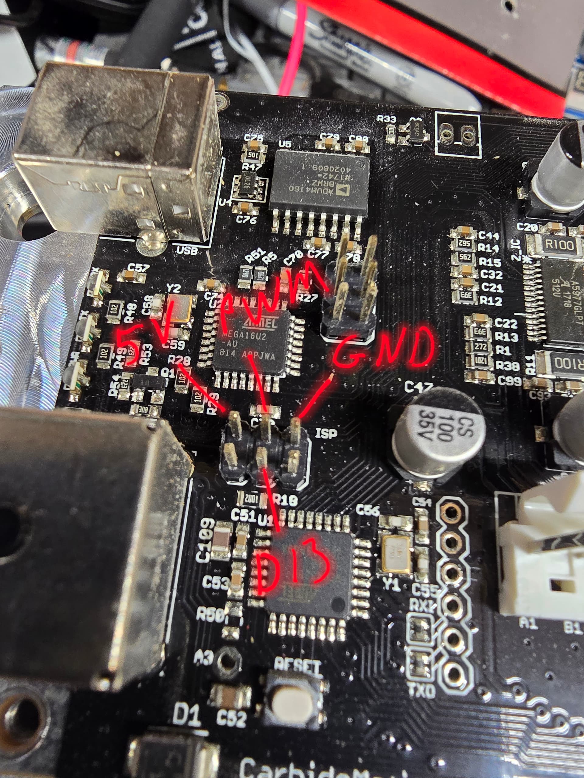
I’ve been rooting around on the internets looking for data on hooking the carbide motion 2.4e GRBL of my shapeoko XXL to the VFD I have in order to control the spindle through the software. I’ve read through several “tutorials”. However, they seem to have conflicting pieces of information in them. Some say I need ground, PWM and 5v pins. Others say I just need PWM. Some say I need a sub board wired in with it.
Most hyperlinks in tutorials and forums are just flat out broken.
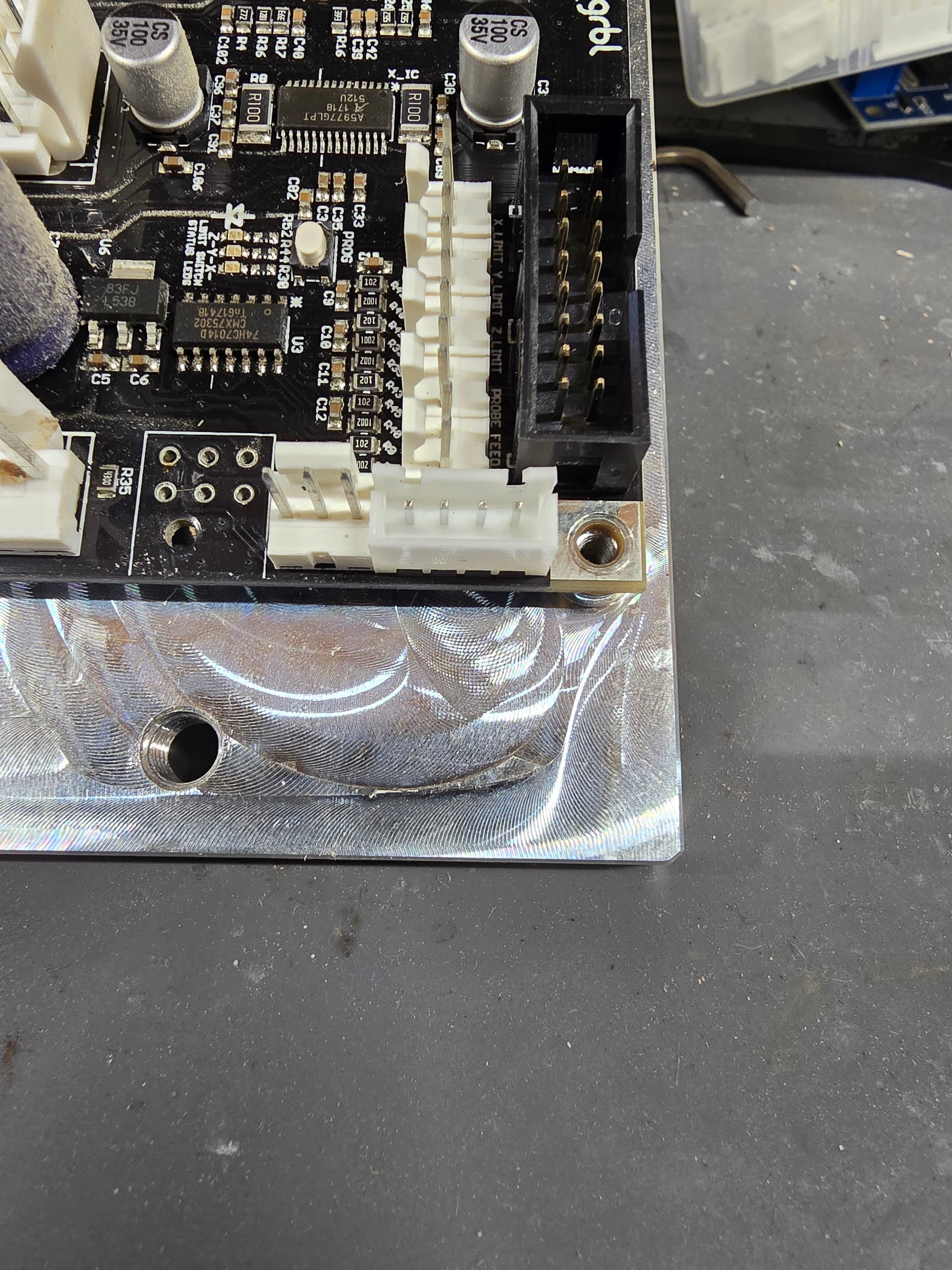
I’m quite comfortable around electronics, and was even going to install an JST-XH-4A connector for ease of installation:
I’m connecting it to this style VFD:
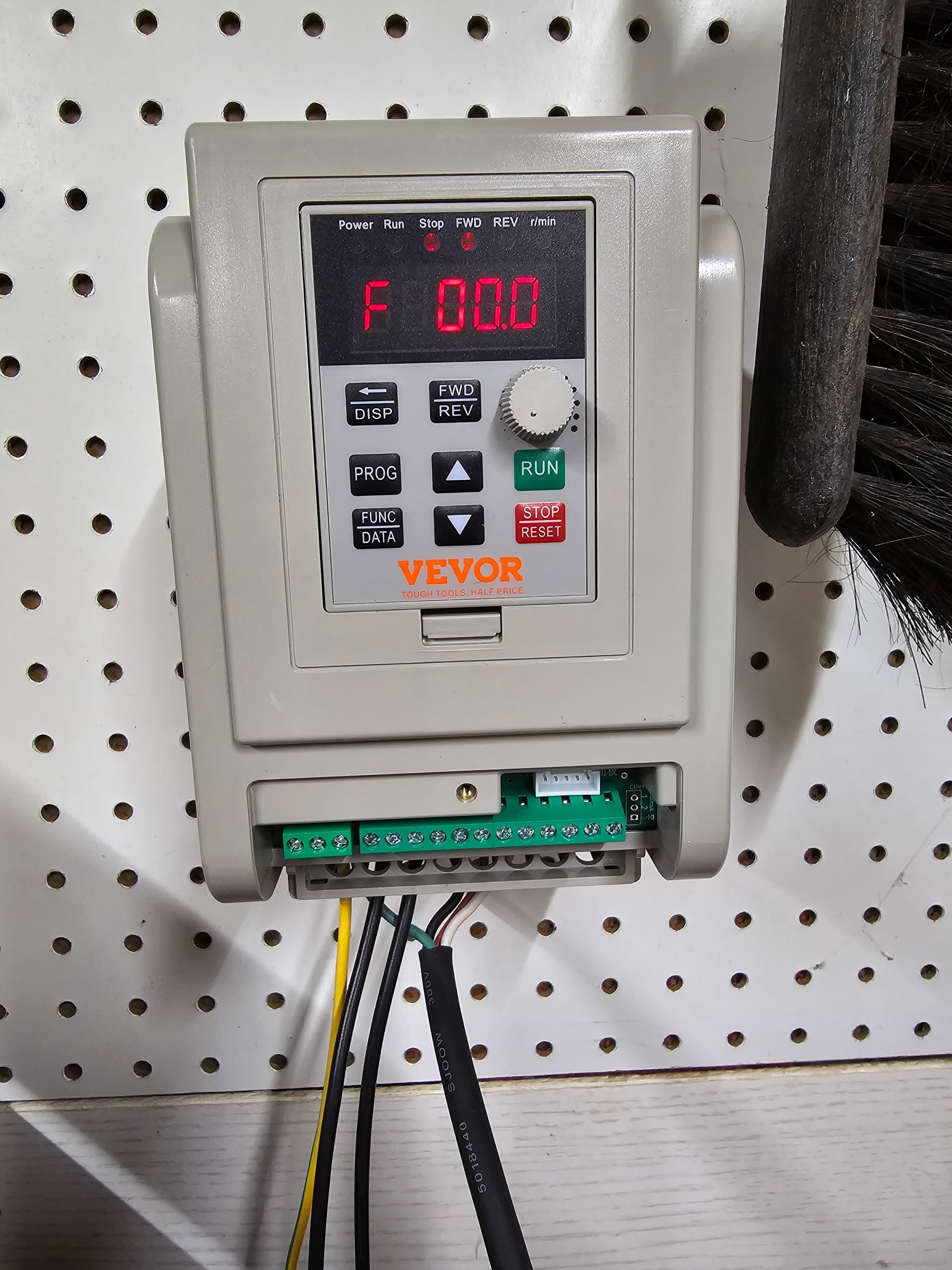
I already have the VFD wired in and I can control the spindle via start/stop button and the RPM with the knob.
My goal is to get the shapeoko software to control Start/Stop and RPM without letting the magic smoke out. I just need to know what wires have to go where, I can likely figure out the rest.
(I’ll also be wiring up an e-stop button, but that’s another story)
Thanks in advance.