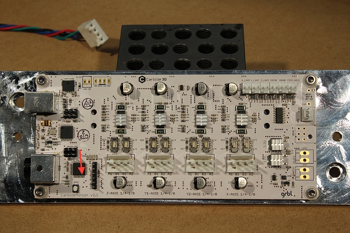
I’m using my Shapeoko 3 to dispense glue, and I control an external dispenser via the spindle control pins on the grbl board. When I send M3 or M5, the control signal changes immediately but there is a 2-second dwell. Can I get rid of the dwell so that I don’t build up a blob of glue at start and end points? I’ve gotten around it so far by turning acceleration and rapid rates way up, but that’s still not as clean as actually stopping and starting the flow for rapid moves.
It’s waiting for the spindle to “come up to speed.” I don’t know how to change that delay without rebuilding code. Maybe someone else does.
If you use the coolant commands instead, it goes on and off when you want it without dwell before the next commands starts. (M7/M8 = coolant pin high, M9 = coolant pin low) Coolant pin isn’t plumbed out of the board, but if you’ve gotten this far, I’m sure you can find it… I think it’s on A3, but you’ll need to check.
I believe this is handled by G04 which is supposed to be supported, from Shapeoko CNC Router, Rigid, Accurate, Reliable, and Affordable :
G4/G04 Dwell (pause) This should probably be calculated to be only one or two spindle rotations for best efficiency. Dwell time is expressed using a parameter (may be X, U, or P) which determines the time unit (seconds, milliseconds, &c.) P, for seconds, is supported and used by Grbl.[6], typically X and U express the duration in milliseconds. All Grbl versions
Carbide Motion
The footnoted thread has the code:
G4 = P120 —> 2 minutes pause
I’m running into the same issue. Is the spindle ramp up dwell adjustable in anyway? otherwise what pins on a V2.2 PCB are for the coolant? I imagine it uses the same ground as the spindle control, but which one is triggered by an M8 and Canceled by an M9?
It’s on A3, but it doesn’t look like it comes out on a header pin. Might be on the reserved stuff, but you would have to ohm it out - it’s pin 26 on the mcu.
So “Ohm it out” meaning its a Pull Down/0v circuit closed or open? not a 5v on 0v off deal like the PWM?
I probed these pins and it was not ad obvious as it was with the Spindle Control (PWM).

I ran some tests to see how 1.1 takes and uses the M08 command. It looks like it totally ignores it.
From the Log:
<Run|MPos:-210.000,-169.675,-5.000|Bf:13,128|Ln:1|FS:5000,1000|Ov:100,100,100|A:S>
(12867): <- <Run|MPos:-210.000,-153.025,-5.000|Bf:13,128|Ln:1|FS:5000,1000|WCO:0.000,0.000,0.000>
(12866): -> N3 G4P0.5
(12865): gc_dwell
(12864): gc_comment
(12863): <- ok
(12862): <- <Idle|MPos:-210.000,-145.000,-5.000|Bf:14,128|FS:0,1000>
(12861): -> N1G0Y-320.000
(12860): gc_motion
(12859): <- ok
The bold looks like where it is getting direct code from the following G-Code I sent. Note the M8 is not shown at all in the log. (note: the log is reverse chronological as it is streeming real time vs the g-code is chrono top to bottom)
M3S10000
G0Y-175
M08
G04P.5
G0X50
G04P.5
G0Y0
G04P.5
G0X0
M05
Any Ideas?
M8 is supported by GRBL, there is a dedicated pin for it (A3). Carbide motion might be filtering it out, try another sender? Or attempt it via the MDI screen as a direct command (/ first)
No. Use an multimeter set on ohms, and see if you can find a header pin (it’s most likely on the left of the board and marked reserved) that is connected to pin 26 on the microcontroller. They are number counterclockwise on the micro from the pin to the left (on the corner) from the “cut corner” in the case. It -think- it’s labeled in the picture below, BUT I HAVEN’T CHECKED IT. I haven’t taken apart my machine to experiment with this at all, I’m going off the GRBL docs, and an old picture of the board I have handy. On the most recent boards there are more reserved/unlabeled pins over on this end of the board, and it may be wired to one of them. It -may- go over to one of the “reserved” pins on the right side of the board on the spindle connector pads (next to the pwm pin).
