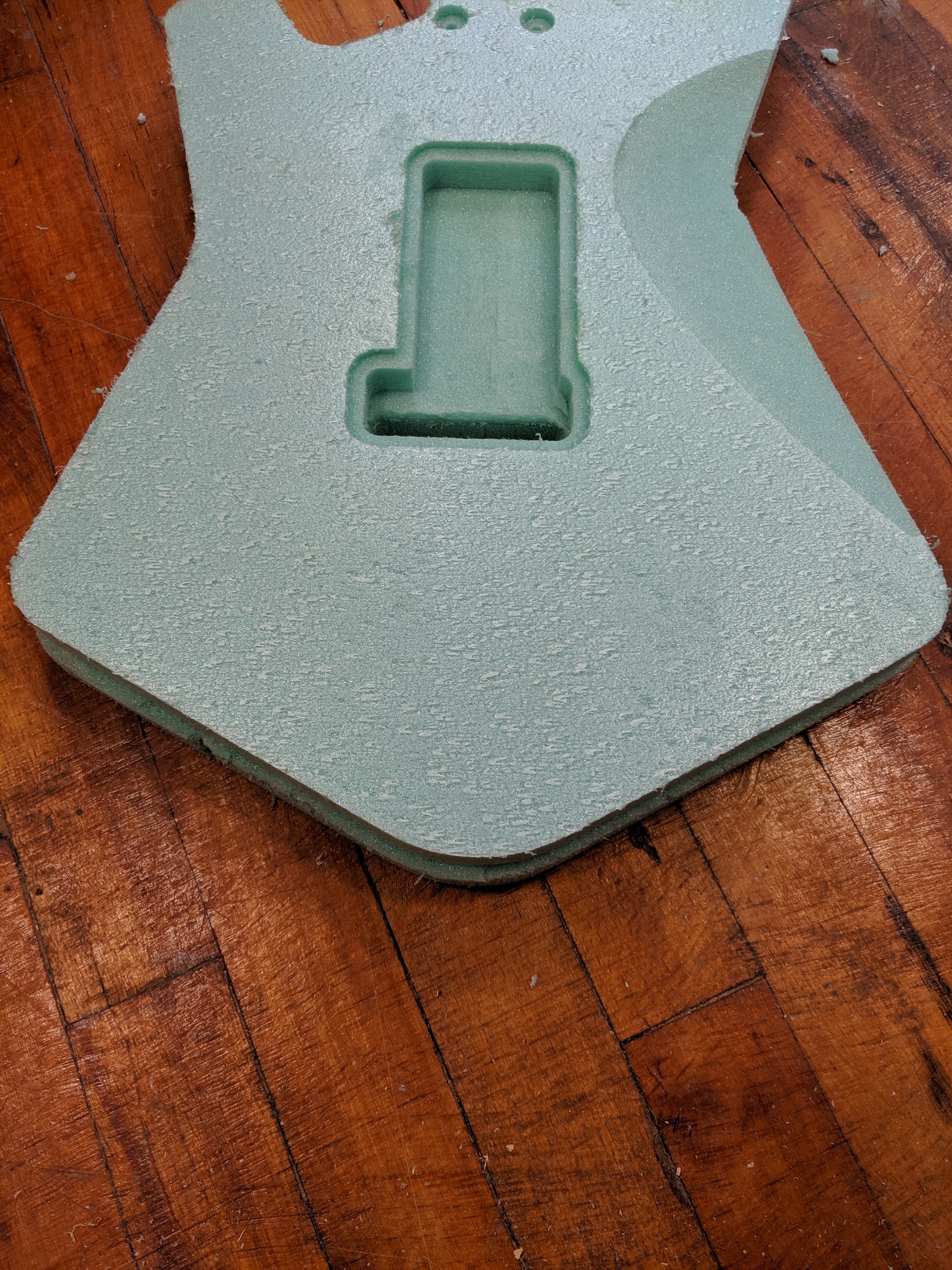
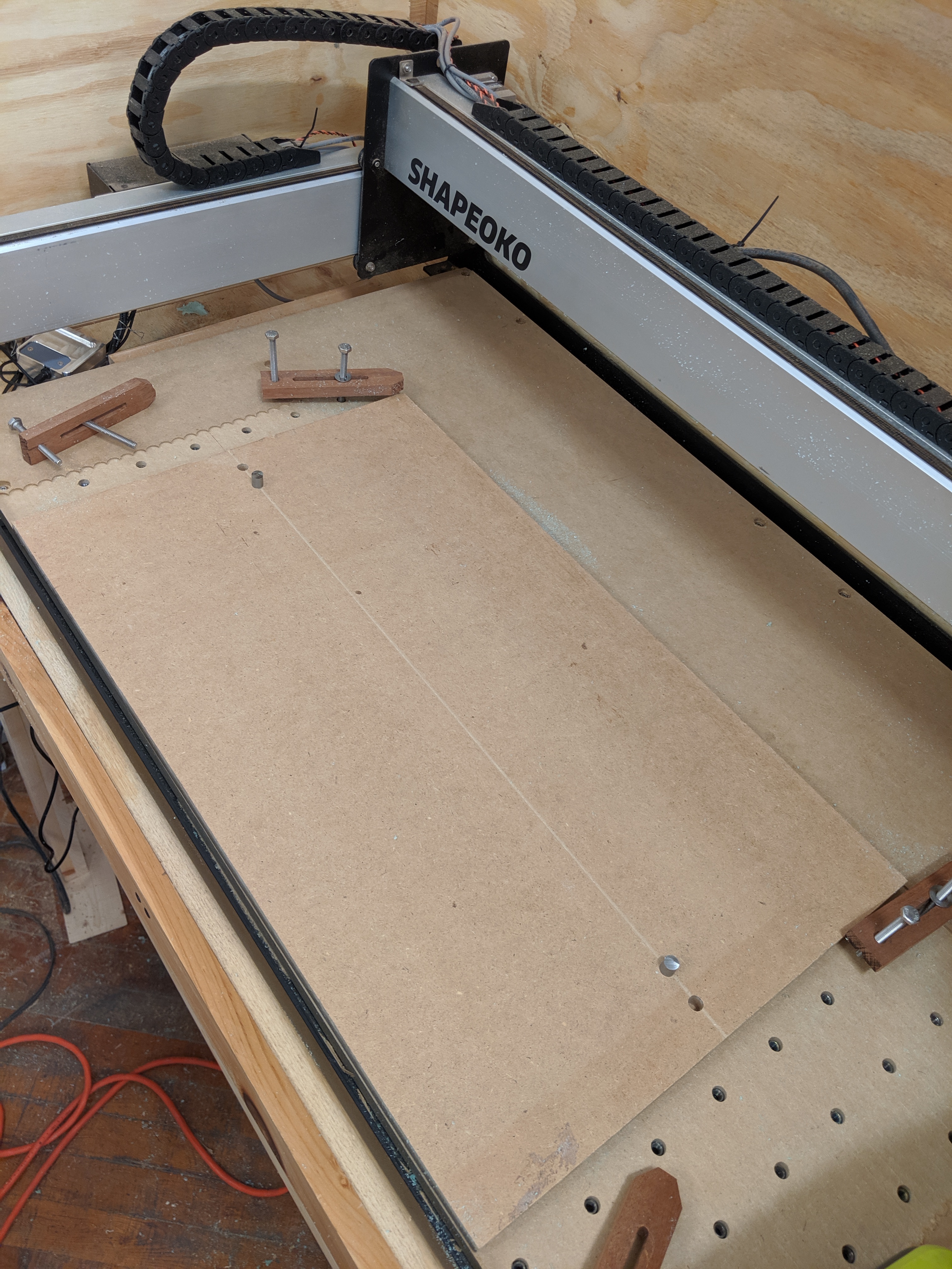
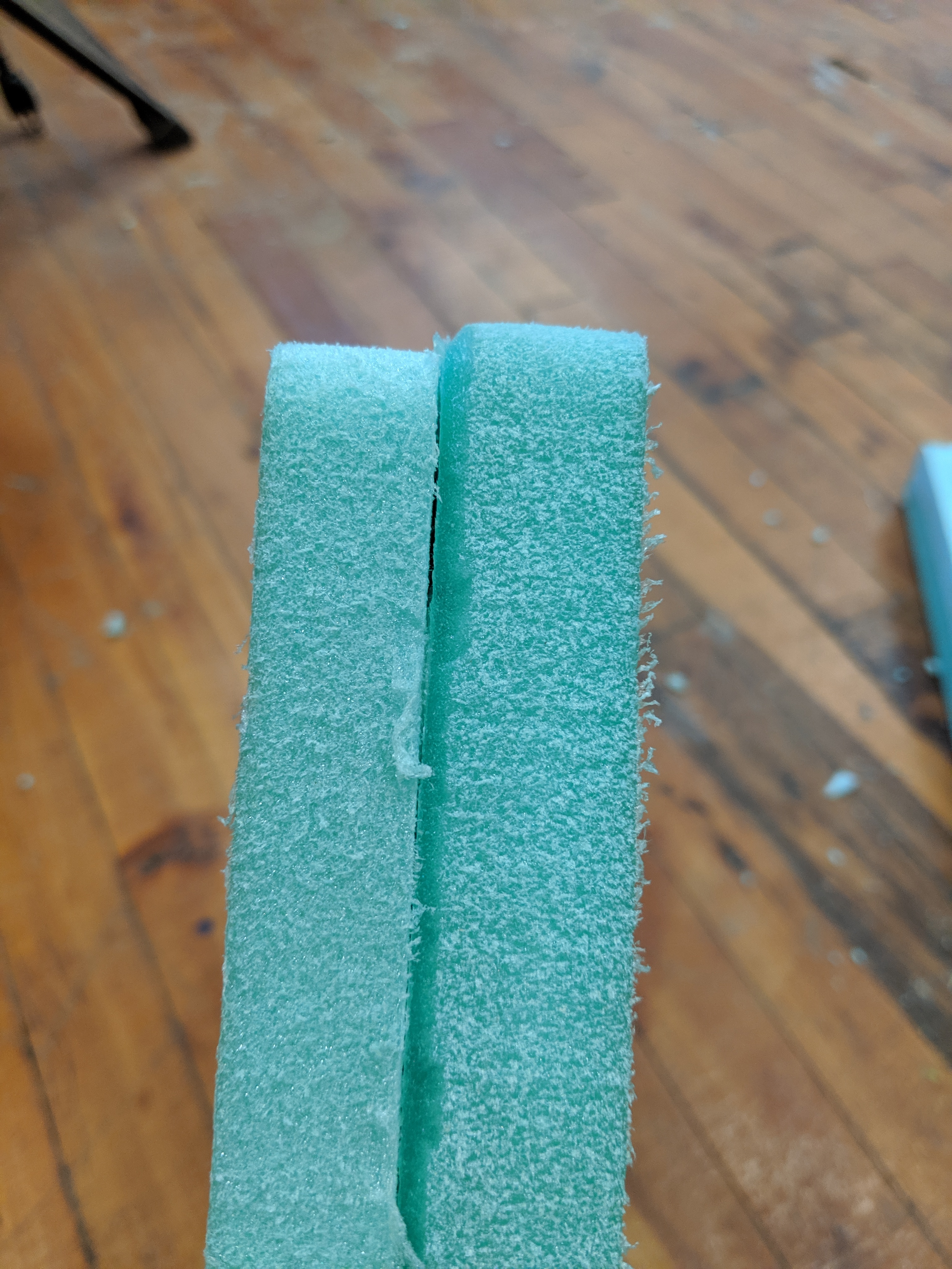
So I’ve been running into a lot of issues when attempting to do 2 side machining. I am attempting to make a solid body guitar on my XL but I am having issues aligning the stock when machining the opposite side. I have been using a 2 pin system with with 1 pin at either end of my center line. I am zeroing at the left most end of my stock’s center line. Despite all of this, the profiles are still skewing along the x axis. I have re-squared my machine and checked all my origins in Fusion but my work is still not lining up. Any Suggestions?
Are the pins a little loose? Are you zeroing once or twice? Does your centerline run from left to right, or top to bottom? Looks like left to right, which makes sense with your description, but what to be sure.
1 Like
Shot in the dark but I had the same problem when my fusion stock round up in setup was different in metric to imperial.
Things would change depending on when I generated the toolpath and posted.
Pins are snug. I’m zeroing once on the right most end of the centerline which runs from right to left alone my x axis.
Hmmmmm I’ll give this a shot. I did have to switch some of my files from inches to mm bc I was getting an error on some of my curves. Perhaps the change in units is throwing stuff off. At this point I’ll try anything haha
Its definitely a frustrating thing to happen! Also make sure you have fusions newest post processor for carbide and you should be fine on arc errors. Been posting strictly imperial for awhile without issue.
I feel ya
1 Like
You might try 3 asymmetric dowels. I’m not sure what CAD/CAM you’re using but I use Vcarve. It allows you to set up the job as a 2 sided job. While drawing the top side of the workpiece, I’ll place 3 asymmetric dowel holes away from the work area and have the machine cut them into the top. Then,in CAD, I’ll flip those dowel holes about whatever axis I plan to flip the piece and have the machine cut them directly into the spoilboard. That way, when I flip the work piece and insert the dowels, there’s only one way it can possibly line up, and that is a direct flip about the axis I want. I apologize if that isn’t a clear enough explanation. Here’s a link (starting at 22:10) to the Vcarve tutorial I use. You might not use Vcarve but the technique will still translate and they may explain it better than I can. Best of luck!
3 Likes
Interested in this as I have been making guitars as well, and getting the 2nd side correct is tough.
I had the same issue and found that it was being caused by my limit switches ( I was re-homing the machine in between sides)
Quick fix: Create the job with Zero in the centre of workpiece, don’t re-home the machine in between sides, just re-set your Z zero
Long fix: purchase more accurate limit switches, BeaverCNC sell them
Not saying it’s what is causing your issue, but it was my issue
I have had good results by zeroing on the center and using the Center rapid position in Carbide Motion however, if there is a problem with the alignment pins between front and back, it could still affect the end product. I used a cradle to align the stock but I don’t think it would work here unless all the contour is cut on the 2nd side.
1 Like
The last thing you want to do between sides is set zero.
The only thing I’m coming up with here is how you set up the original pins in the wasteboard. The last time I did this (been a while) I created a part with the dowel holes in it that I could align exactly in fusion (the wasteboard part was flush up against the to-cut part, with the pin holes “fixed jointed”). I turned off the part I wanted to cut, created the toolpath for the pins (I used zero on the wasteboard, 1/2 way between the pins). Moved the axis to the “top of stock box”, Then I turned off the “wasteboard” part, turned on the to-cut part, flipped the axis, generated the toolpath for that side, then flipped the axis and moved it on the Z axis to bottom of stock box, generated the last toolpath. Because I was zero in the center (and didn’t change tools) there wasn’t a need to move the axis around besides top, bottom. When I cut, it was pins, bottom side, then top side, all with the same tool, so I didn’t need to rezero anything. The only thing that comes to mind that might be a problem (because the whole process described here seems ok) is the original alignment of the pins against the axis of the part.
Hi,
Having the same problem. I’m getting a clockwise rotation of approx. 1.5 degrees (clockwise) after flipping about the two dowels located on the Y axis. (Flipping stock left-to-right).
Any updates on whether the rounding issue, metric vs. imperial is a fix? I’ll try that next.
Success! I ended up plunging a 1/8 inch hole in-between the dowells on the centerline and using that to zero instead of using the right most end of my center line. Thanks for all the help!!
3 Likes
I can’t open the image, maybe you can reload.
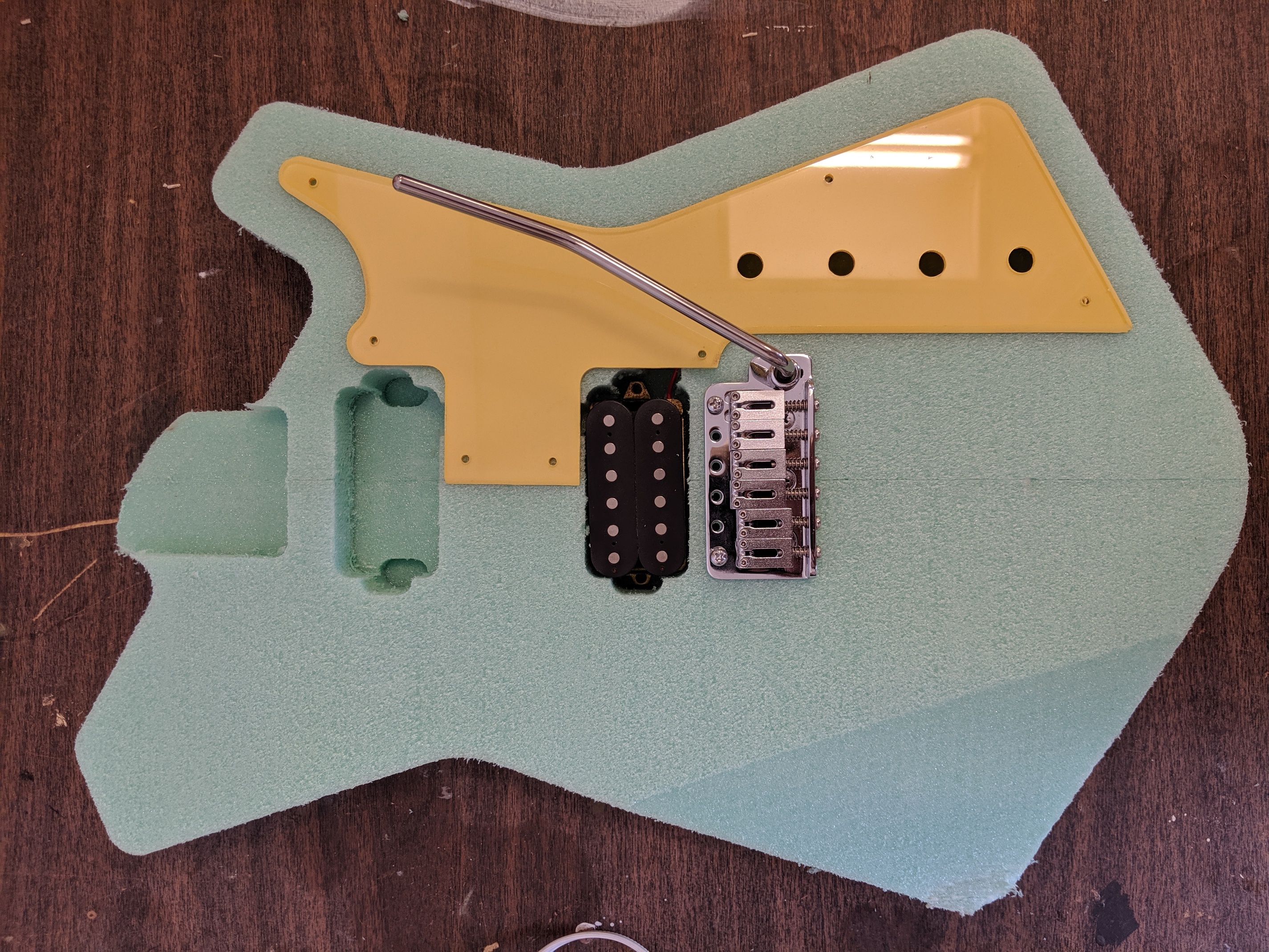
That looks reeeeeallly cool!
1 Like
So cool, glad you got it sorted!
This topic was automatically closed 30 days after the last reply. New replies are no longer allowed.