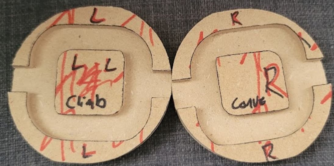
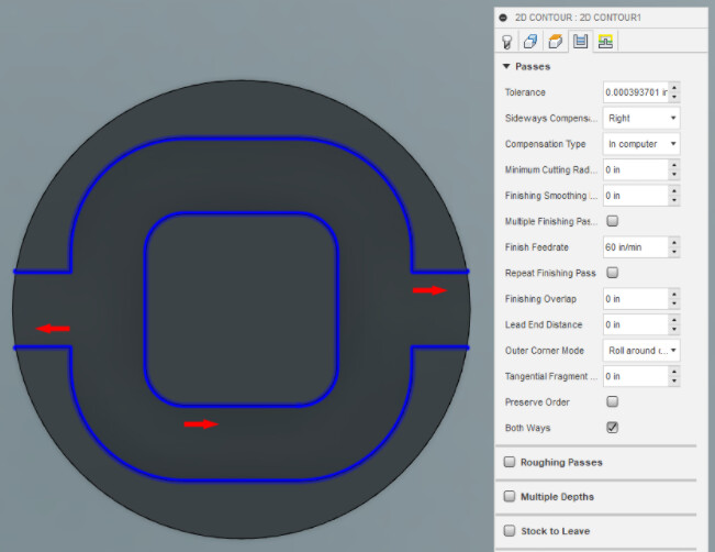
I’m guessing/hoping this is a noob issue. I’m new to CAM on Fusion 360. I have a Shapeoko Pro CNC router. I’m trying to cut just a test part/program to learn the process. I’m running into an issue with the rounded contours of my parts. It seems to be related to the right/left sideways compensation of the toolpath. I’ve tried adjusting feed rates, switching the compensation type from “In program” to “off”, and the “both ways” setting on & off. I was about to try adjusting the minimum cutting radius, but it seems like this would only help with the inside corners that are wrong. My “right” compensated parts are a perfect mirror to the “left” compensated parts, in the ways they are out of round and corners made sharp. Parts also come off the machine really consistent from part to part. I hope this is an easy fundamental fix. thanks in advance for the help.
I think most people don’t touch those parameters. I think if there is a problem it is more likely a problem with your mechanicals: belts, pullies, and V-wheels.
Edit: nevermind the V-wheels, see you have the Pro.
What was the issue with the first part that prompted you to look into this? MDF is so easy to machine I doubt climb/conventional has any influence on forces.
If I understand what you’re talking about right, that controls how the tool diameter is accounted for. You ALWAYS want “In computer”. GRBL doesn’t allow anything else. Only exception might be something like a laser cutter.
See Cutter Compensation for Beginners for more details.
Leave that off. “both ways” allows CAM to use both climb and conventional milling. It can result in a faster toolpath at the cost of maybe not as nice a finish or reduced tool life.
As for the problem itself, it’s hard to say because I don’t know what the part should look like and what exactly you’ve done in CAM.
Can you post a picture of how the parts you cut should have looked (e.g. a screenshot from CAM)? Maybe you can share your files somehow?
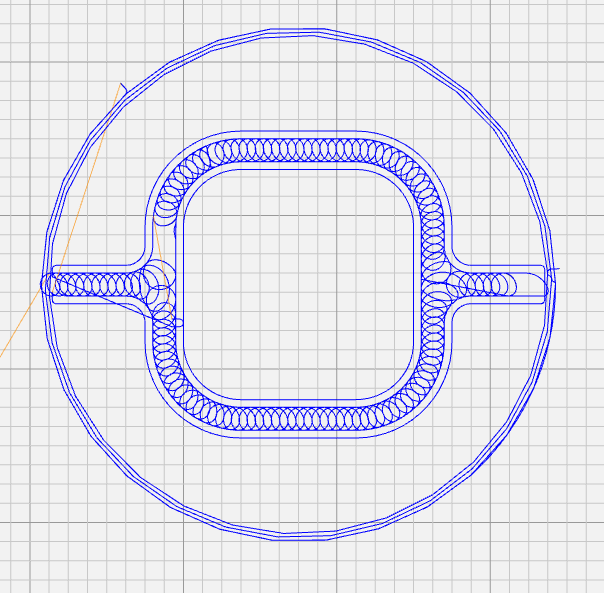
Can you show what your toolpaths look like?
There’s some interesting experimental results on this guy’s channel about that

Thanks for the responses, @kelaa , @Moded1952
I’ll post a picture below of what the part should look like. The parts should be symmetric across a vertical plane. The issue I think I’m seeing is that every other corner appears to be cutting on the “wrong” side of the contour.
The first thing I thought was I must have a machine assembly issue as well. I went through everything I could think of mechanically and couldn’t find a smoking gun, so I started down the tool path.
I switch the sideways compensation from Right to Left (Conventional to Climb) and the incorrectly cut corners and correct cut corners mirrored on the part (as seen in the original posted picture). They are also near perfect mirrors, so I cut some another “Right” and it’s very consistent to the right shown in the original picture. So due to the consistency of parts coming off the machine, I feel like it has to be a programing issue.
Maybe I need to break up the contours to get them all on the correct side of the line. My hope was there is some compensation input in the tool setup or the contour setup that I’m missing that would fix the issue. But if anyone has ideas of specific things to look for on my machine or in carbide motion settings or something I’m all ears.
Yeah, I have “Both Ways” turned off now. Especially because it did not change the corners that were cut on the wrong side of the contour. Even with “both ways” on the parts came out like the parts thein the original post, dependent on the LEFT or Right compensation selected.
As Lucas suggested, it’ll be a lot easier if we can see the CAD CAM model.
If you file / export the F3z file, zip it into a zipfile you should be able to attach it to this thread then we can see the detail of the toolpath setups.
I think your radar is way off here but it’s easy to rule out: put the generated G-code into a G-code viewer and see if there are uneven curves in it. Yes: it’s a definitely a CAM problem. No: it’s the machine’s fault or an issue with your feeds/speeds or something else.
Also +1 to Liam. It’s a lot easier to help when we can see the actual files.
Thanks @Moded1952 and @LiamN
I’ve never used a Gcode viewer before, honestly didn’t know they existed. I popped my .nc file in there, and it looks right. You guys are totally right, must be something wrong with the machine. I was totally had myself sold in the wrong direction. Thanks again!
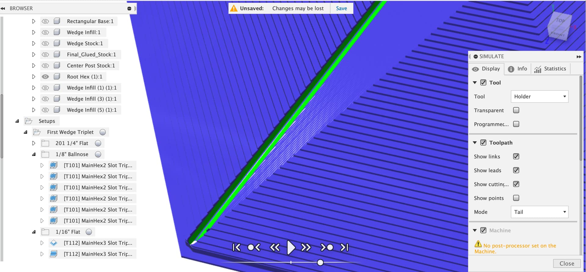
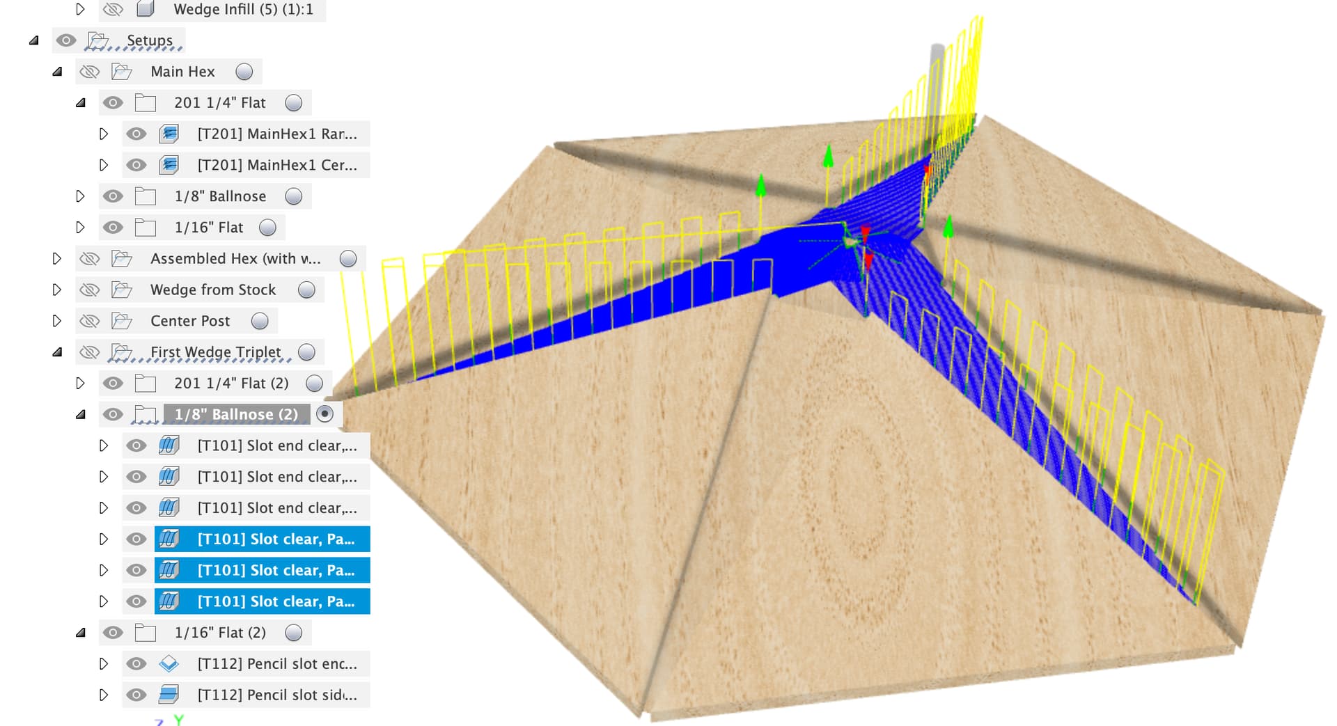
In Fusion I always turn on the stock and watch the toolpath simulation for a job before running it too.
You can run it in stock comparison mode where you see the final model in green, extra stock in blue and cut away model in red
You can also just see the toolpaths on their own
This topic was automatically closed after 10 days. New replies are no longer allowed.