I Trying out some 3D STL carves and I’m having problem on vertical surfaces being very rough even with finishing runs with an 1/8 inch ball mill and 10% stepover?
Thoughts
I Trying out some 3D STL carves and I’m having problem on vertical surfaces being very rough even with finishing runs with an 1/8 inch ball mill and 10% stepover?
Thoughts
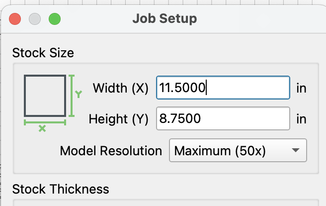
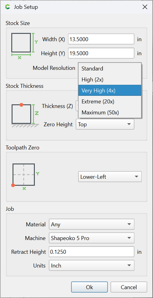
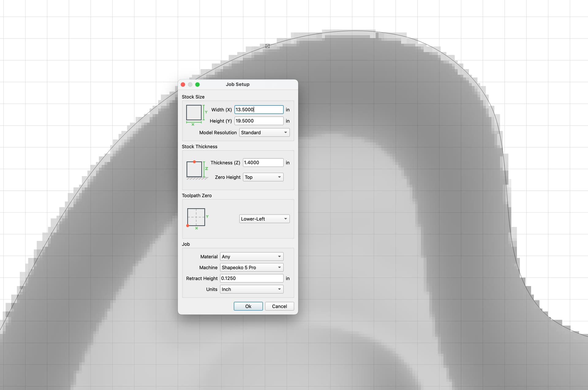
If you go under the gear to where you put in the material dimensions, there’s a little dropdown at the top for “model resolution”, change that to something higher. I do mine at the top resolution and it takes longer to calculate the 3d stuff but looks excellent
We’d have to see files and a photo to help diagnose the problem.
If you do this, you’ll need to go back to your model and make some changes, they can be superficial like removing some extra zeros or something, but CC will need to be forced to re-calculate your model.
You can tell if it worked by zooming in close to the 3d parts, especially curves, and if it looks pixellated, it needs to be re-rendered. if it’s nice and smooth, it’s fine.
Just for reference, 10% stepover is what I would consider to be a good “general purpose” quality finish. 5% is where I’d go if I wanted a better finish.
Spacing or stepover on a 3D path is calculated on a plane, so as the contour gets steeper, the actual stepover on part is greater. If possible, set the angle so it’s cutting up & down the steep areas rather than traversing them…
Excellent explanation @Tod1d . I did not know that so thank you.
Thats one reason I do 2 finishing paths, the first across the grain, the second with the grain.
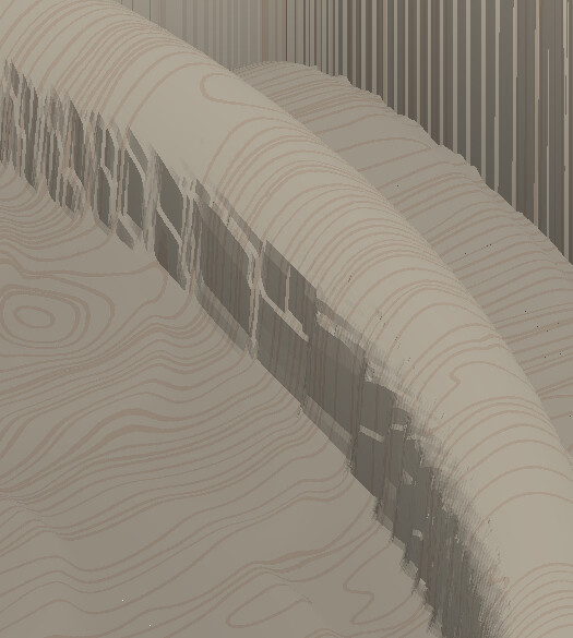
I did a lot of finish sanding already so the final project doesn’t show the issue but you can see it in the
I’ve been a 45deg to the grain convert lately
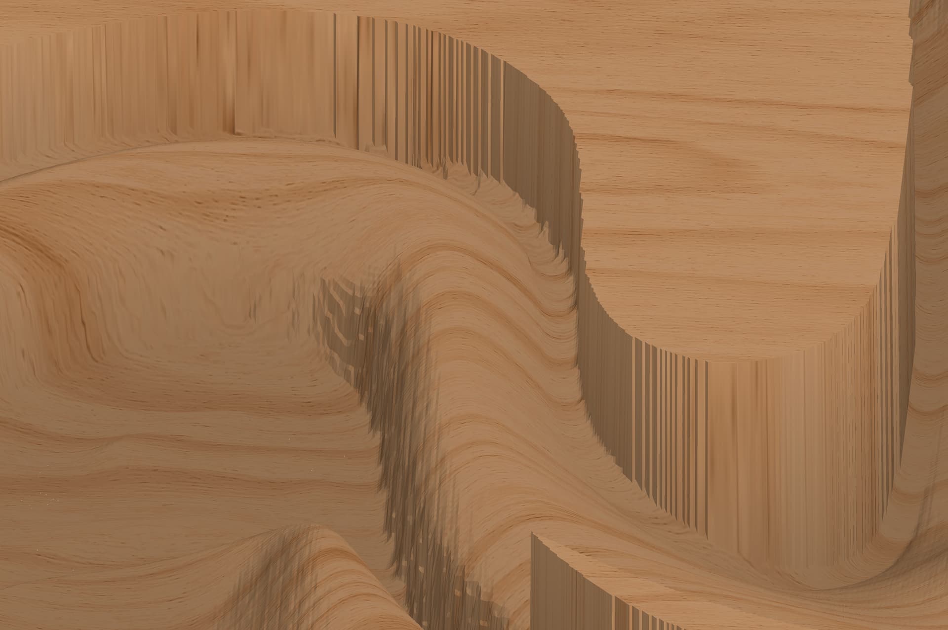
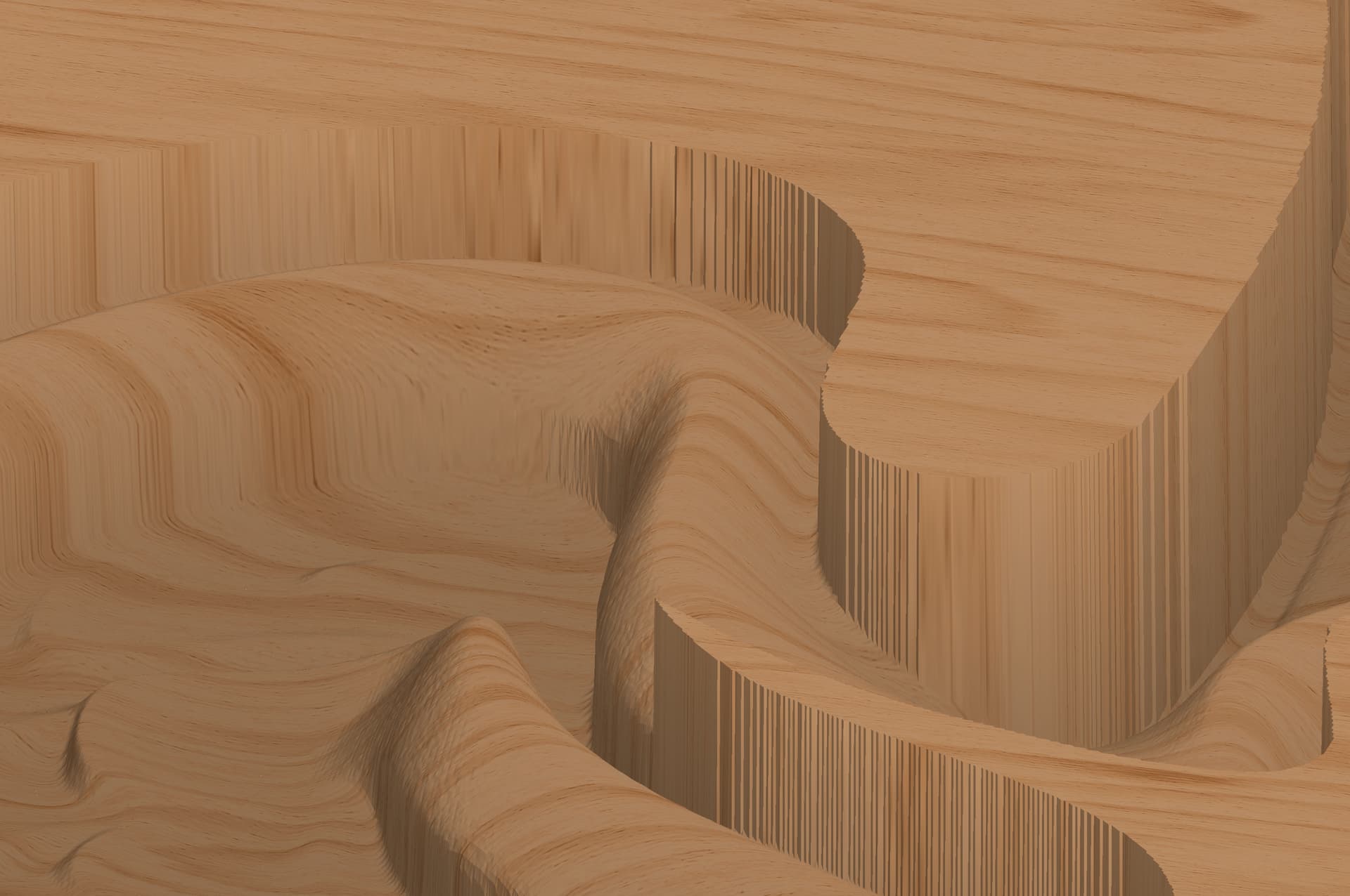
Attached is an example file of how vertical parts of the 3D object are very rough. Appreciate any insight on how to eliminate.
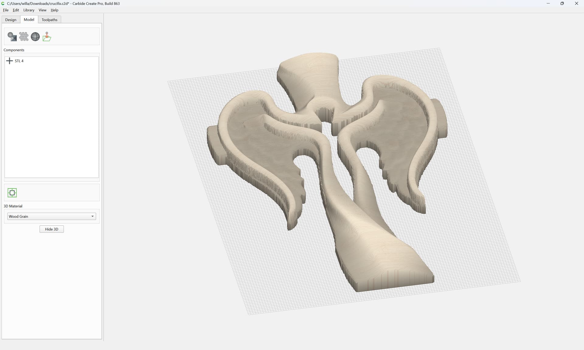
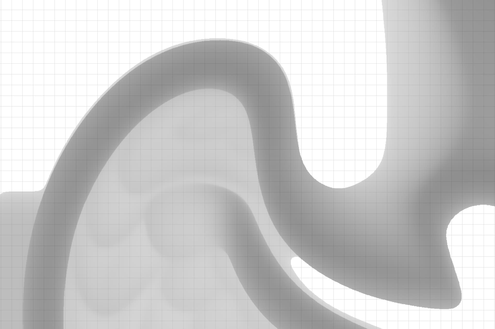
That file previews as:
while the 3D model previews as:
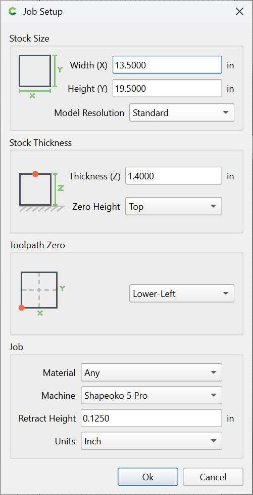
The model resolution is Standard:
so my first thought would be to set to Very High or higher:
and adjust things until the model is as desired, then for the toolpaths, offset by a bit more than the radius of the largest tool which will be used and use that offset geometry for the toolpath, selecting tools which have sufficiently long cutting flute lengths for the vertical features and cutting at multiple angles.
Alternately, if the original was a 3D STL, perhaps use MeshCAM?
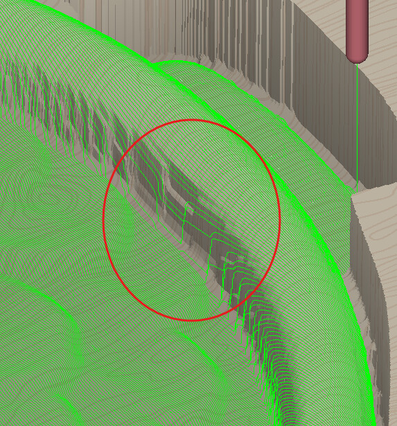
Take a look at the inside of the wing
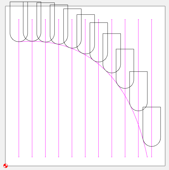
Now look at the toolpath
See how far apart the stepovers are?
The only way to alleviate this would be to cut it twice at opposing angles.
Another option is to use a rough 3D path as a finish path with 0.0 stock to leave, a large stepover (max 3.9"), and a small (0.010") depth of cut. This essentially does a Z-level finish path.
Here’s an example rough_finish_3d.c2d (1.7 MB)
sometimes I wish we had a radial 3d path option.
A Scallop tool path works well. I use it Fusion for carves all the time.
An excellent aspect to MeshCAM is that it has both parallel and waterline finishing toolpaths, and you can set the angle range for each (independently so they can overlap) to accommodate both steep and shallow contours.
I downloaded your file and took a look at it and the clear fix for this is to change the quality level of your project as @WillAdams said above.
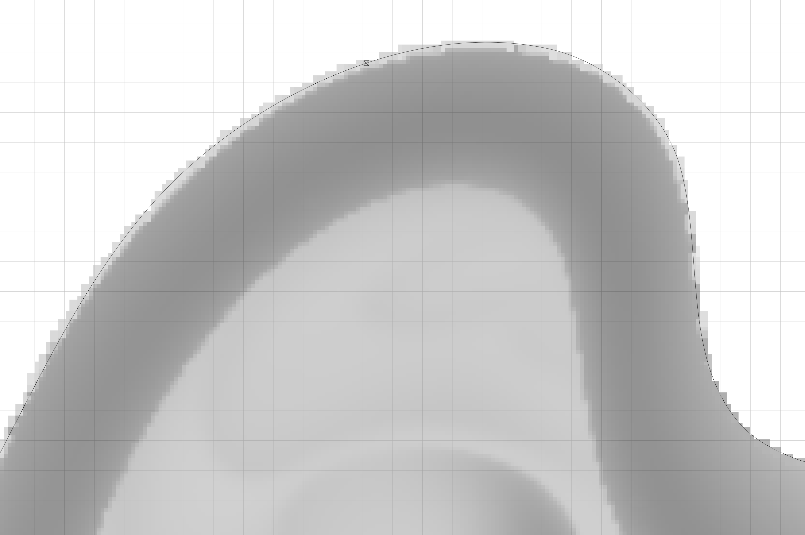
If you zoom in on the height map of the imported file, you can see how incredibly pixelated it is.
The big thing to remember as you try different quality levels is that you have to go into the 3d item and make a superficial change to any value so that the “Apply” button enables. That way when you click “Done” it will fully re-render the item and you’ll see the effects of the different quality levels.
Thanks for all the help
Best regards