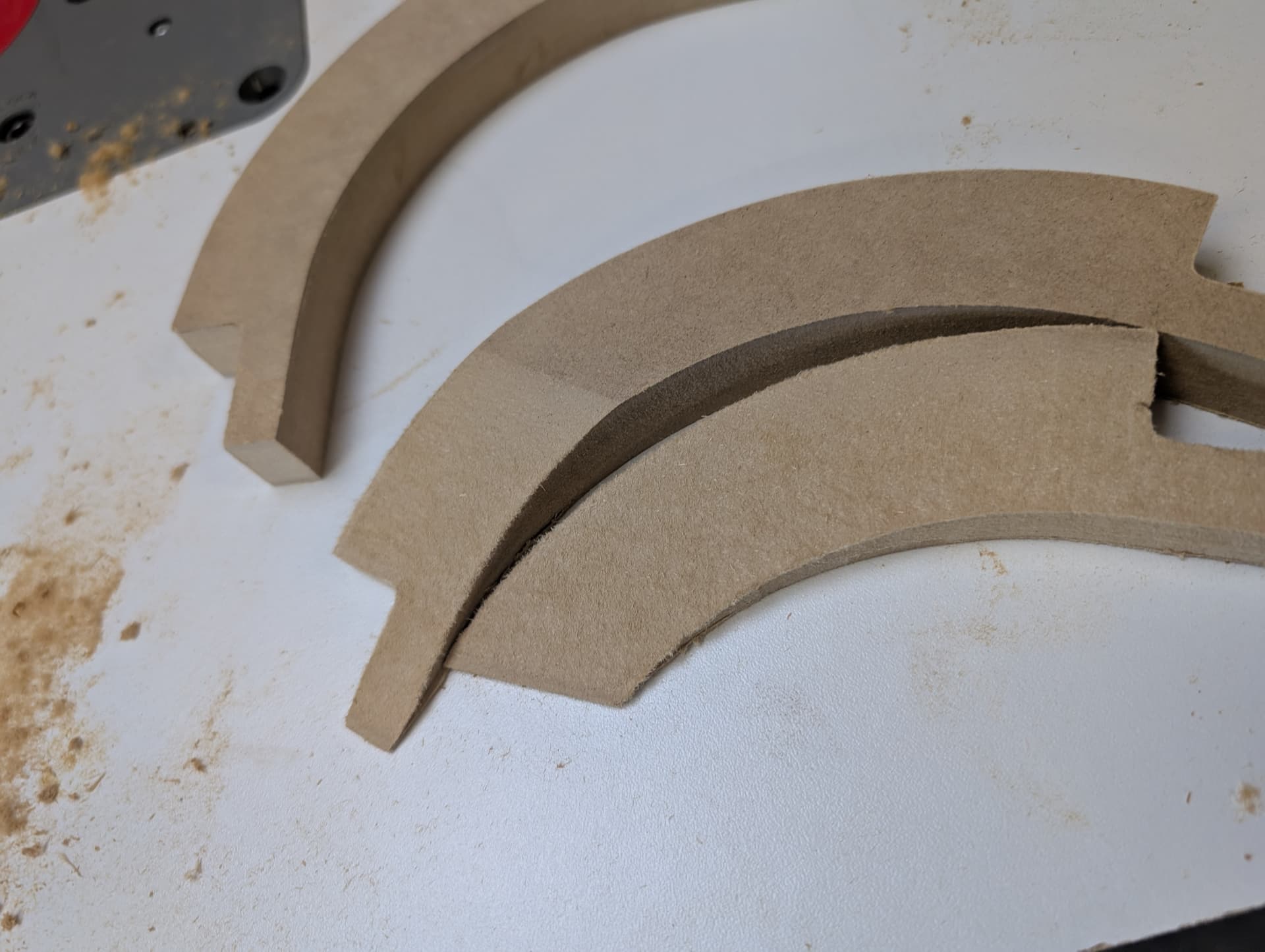
I am trying to cut some beveled curves, so I giving the Carbide Create Pro 14 day free trial a try.
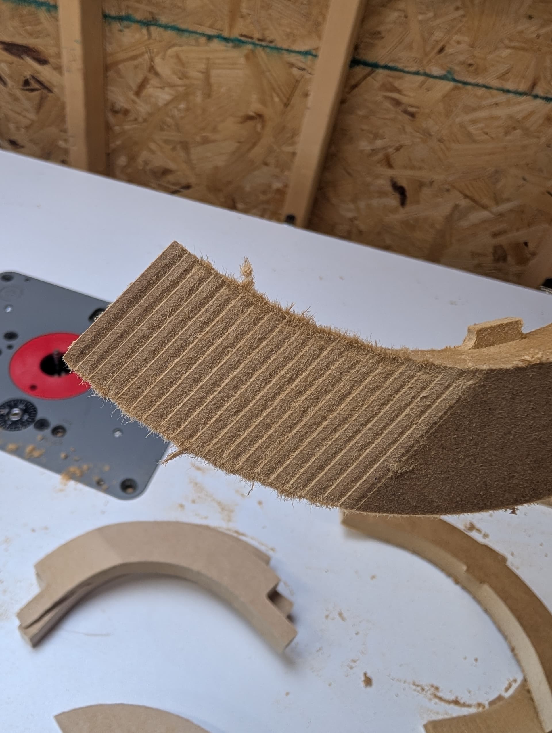
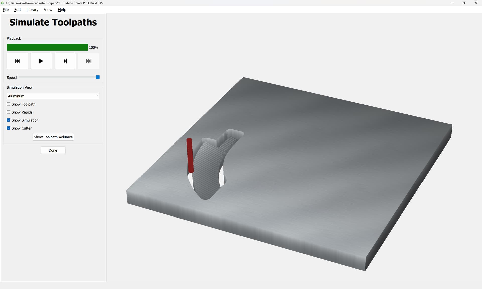
The fist attempt came out OK. The machine moved along the curve cutting deeper as it appeared to simultaneously move in all three axis at once. The only issue is that the machine did not cut all of the way to the bottom of the 3/4" MDF, but that may be an unrelated problem as I have had the same problem on some other projects.
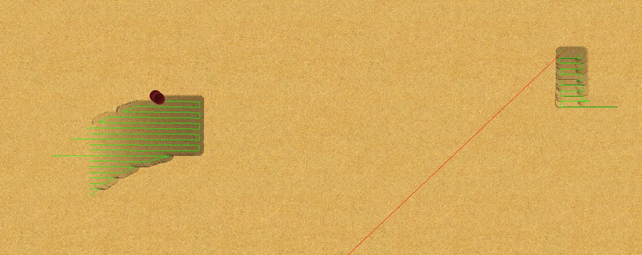
Playing around with the simulator it looks like the machine wants to cut left to right (the x axis) and I should be able to avoid the stair steps if I orient the piece so the bevel is left to right. But, these are curves so the bevel orientation could possibly be any direction.
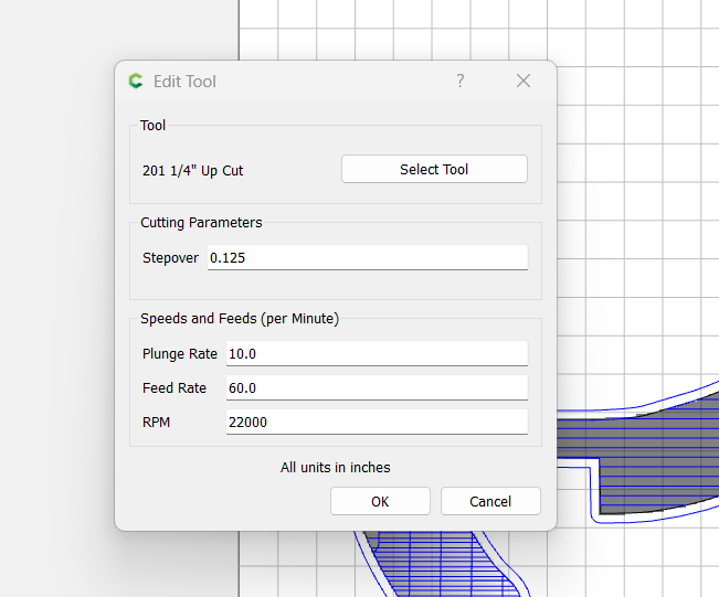
Both cuts were made with the #201 up cut bit with a 0.125 step over.
Why does the machine seem to want to cut left to right?
Is there a way to force the machine to to cut along the curve, all three axis moving at once?
I have a quarter inch ball nose I am assuming I will get a better stair-steps if I use that bit?
What about the step over, I try to avoid small step-overs to save time. Dropping it down to .0625 or even lower will still make stair-steps, they will just be smaller, so I don’t see the advantage to cutting slower to get a bad result.
How does the geometry which limits the 3D toolpath area relate to the 3D model?
Note that Carbide Create Pro only considers the 3D Model w/in the geometry associated w/ the toolpath and positions the tool at its center along that perimeter, so may over-cut by the tool radius — to prevent this from happening, ensure that the 3D model has structure surrounding the region to be cut out and it may be necessary to include it in the region for the toolpath.
I cannot upload the file, it is to large. Is there a way to compress the files? The original file had six parts, I had to delete all but one to upload the file.
Nothing in there to control the direction of the cut.
“How does the geometry which limits the 3D toolpath area relate to the 3D model?”
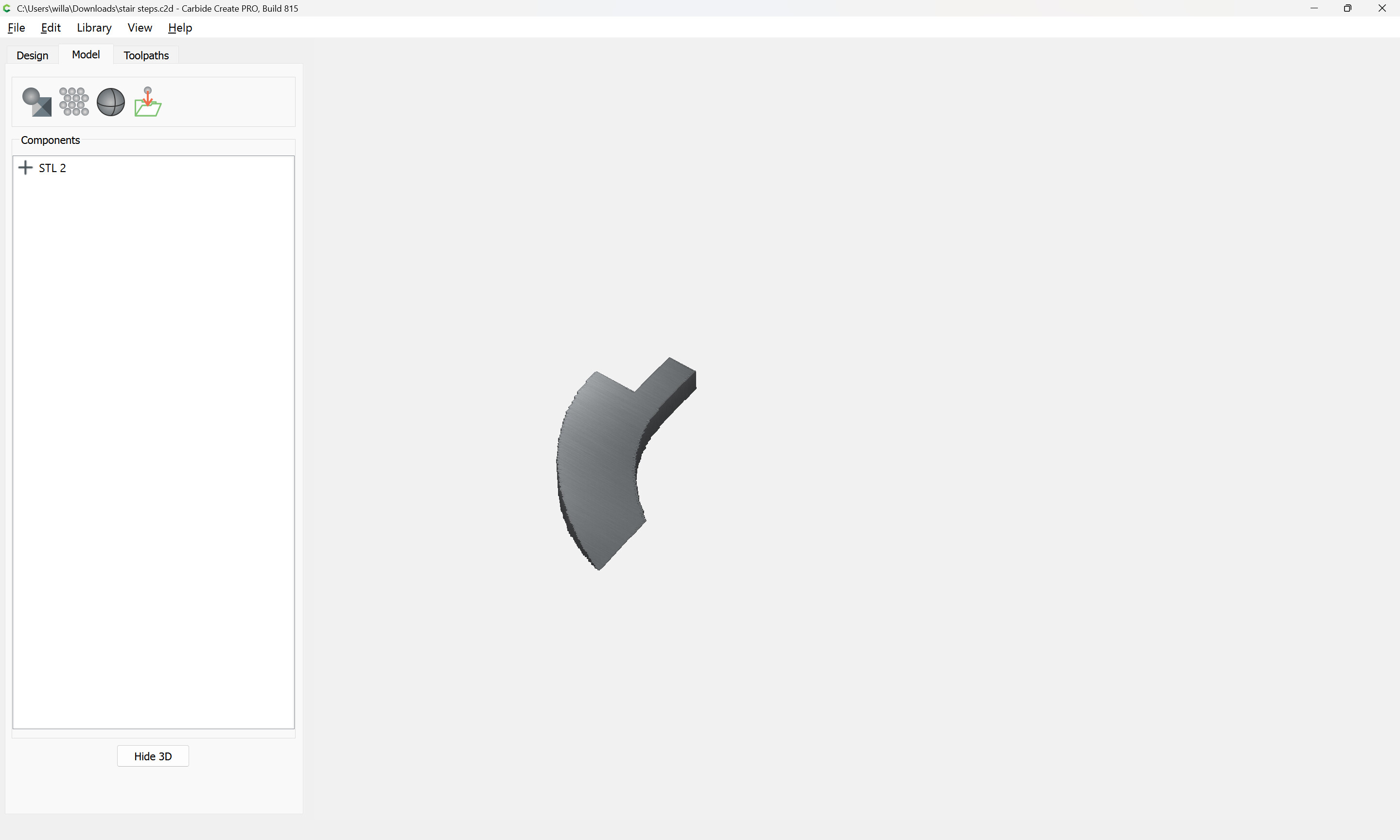
I do not understand what you mean. I right clicked the model in the model components list and Selected “Create Outline Vectors” and used that to make the toolpaths. Is there a different way to do it?
“Note that Carbide Create Pro only considers the 3D Model w/in the geometry associated w/ the toolpath and positions the tool at its center along that perimeter, so may over-cut by the tool radius — to prevent this from happening, ensure that the 3D model has structure surrounding the region to be cut out and it may be necessary to include it in the region for the toolpath.”
I had no problem at all with the shape of the cut, that was fine, the issue is the stair steps, I need a smooth surface. If I have to sand it smooth then why do I need this expensive CNC?
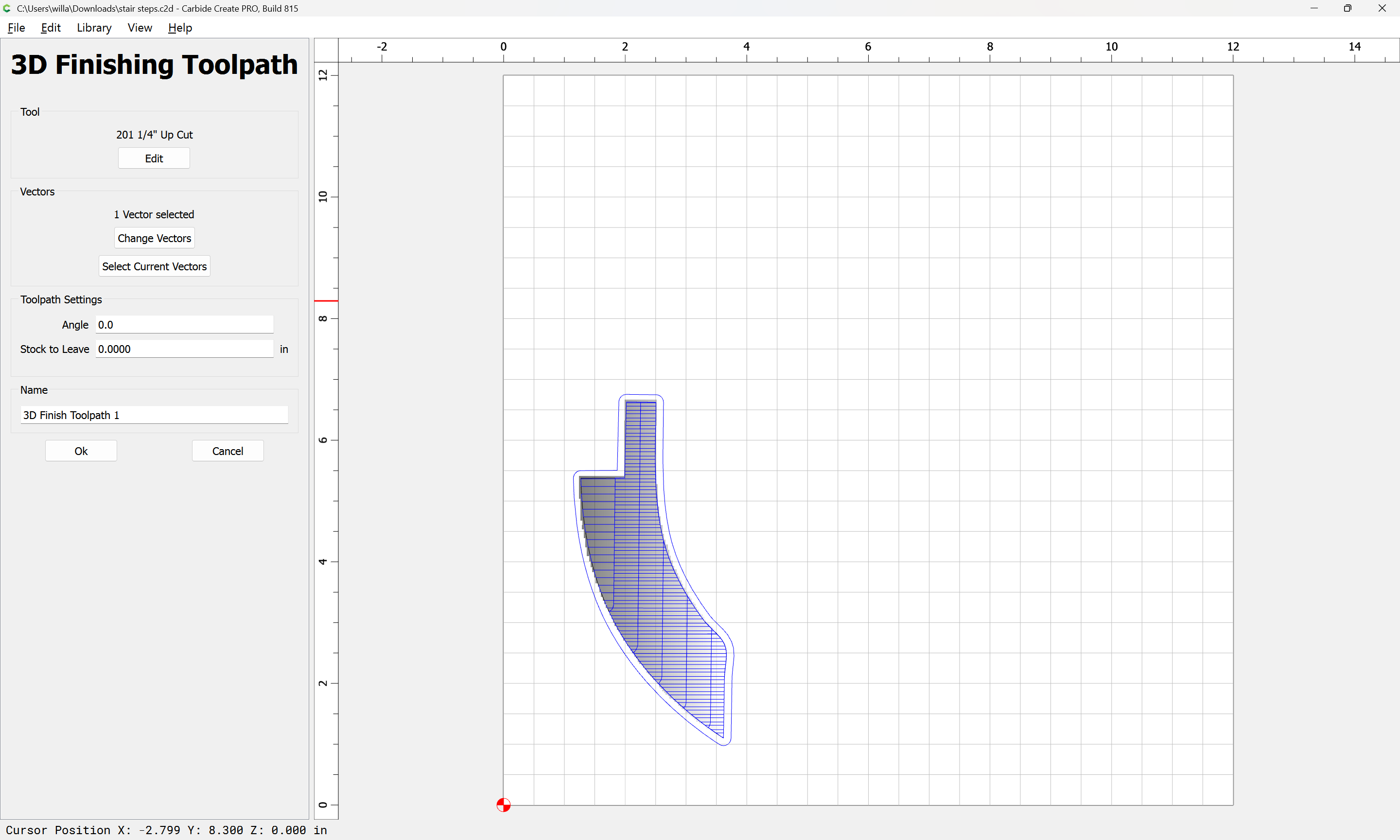
If you’re cutting this with a flat endmill, I think 0.0° is the angle you want. As straight up/down hill as possible. Reduce the stepover to get smaller scallops.
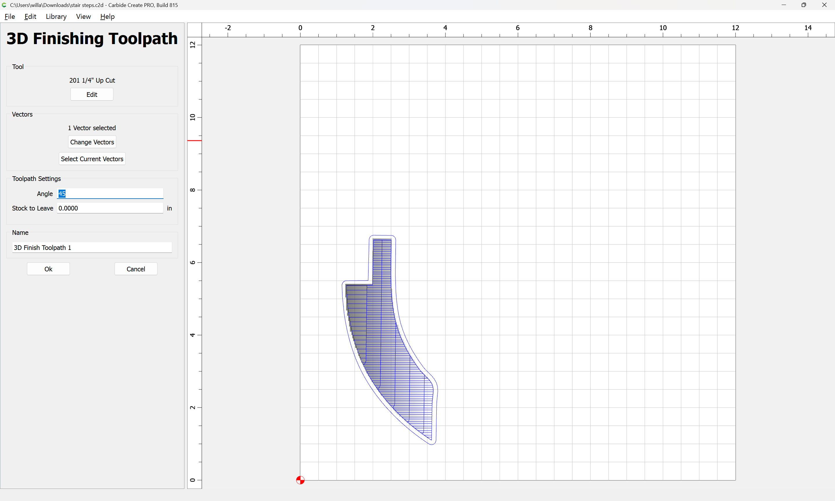
While you were doing that I was tinkering with the model, and it seems that rotating the model itself seems to get the same result. PLUS this time the simulation seems to show that the machine will make a pass in both the X and the Y direction.
I had originally placed the pieces on the work surface to minimize waste, now I have them rotated to get a smooth cut.
Perhaps by adjusting the angle of the model I can do both at once.
The odd thing is that I used the exact same settings for two different cuts but one gave me stair steps and the other did not. My goal is to make something that I can reliably batch out and potentially sell (yes, I do think people will buy these little curved wedges). So I need to figure out why one method works and the other does not.
I have a ball nose quarter inch end mill, I can swap it out if that will give better results. But changing the bit takes time and I need to figure out a way to design projects that can be cut without changing bits.
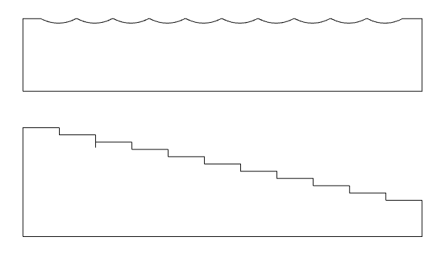
If you use a flat endmill & cut up & down the slope, a cross section of the cut will look like the first image. If you cut across the slope, and cross section will look like the 2nd.
A ball mill in either direction will give you curved scallops like the 1st image. Stepover controls the height of the scallops.
Whether you change the angle of the cut, or rotate the part makes no difference.
So, if I want a flat surface a ball nose is a bad idea, as it will take a very small step over to get a flat surface.
So what we have here is the fist or second chapter of most calculus textbooks. As the step over approaches zero the number of stair steps approaches infinity and eventually converges to an incline plane. Each time the step over is cut in half the cut time doubles. How small of a step do we need so that the human eye cannot see the stairs?
You can’t get a flat angled surface with a round cutter. Unless the cutter matches the angle, like in a multi-pass chamfer. The endmill will give you a flatter surface using the same stepover than a ball mill, as long as you are cutting straight up-down hill, rather than across the hill.
As the steepness increases, the difference between the ball & endmill diminishes. But for a gradual shallow incline like you show, the endmill will be more efficient.