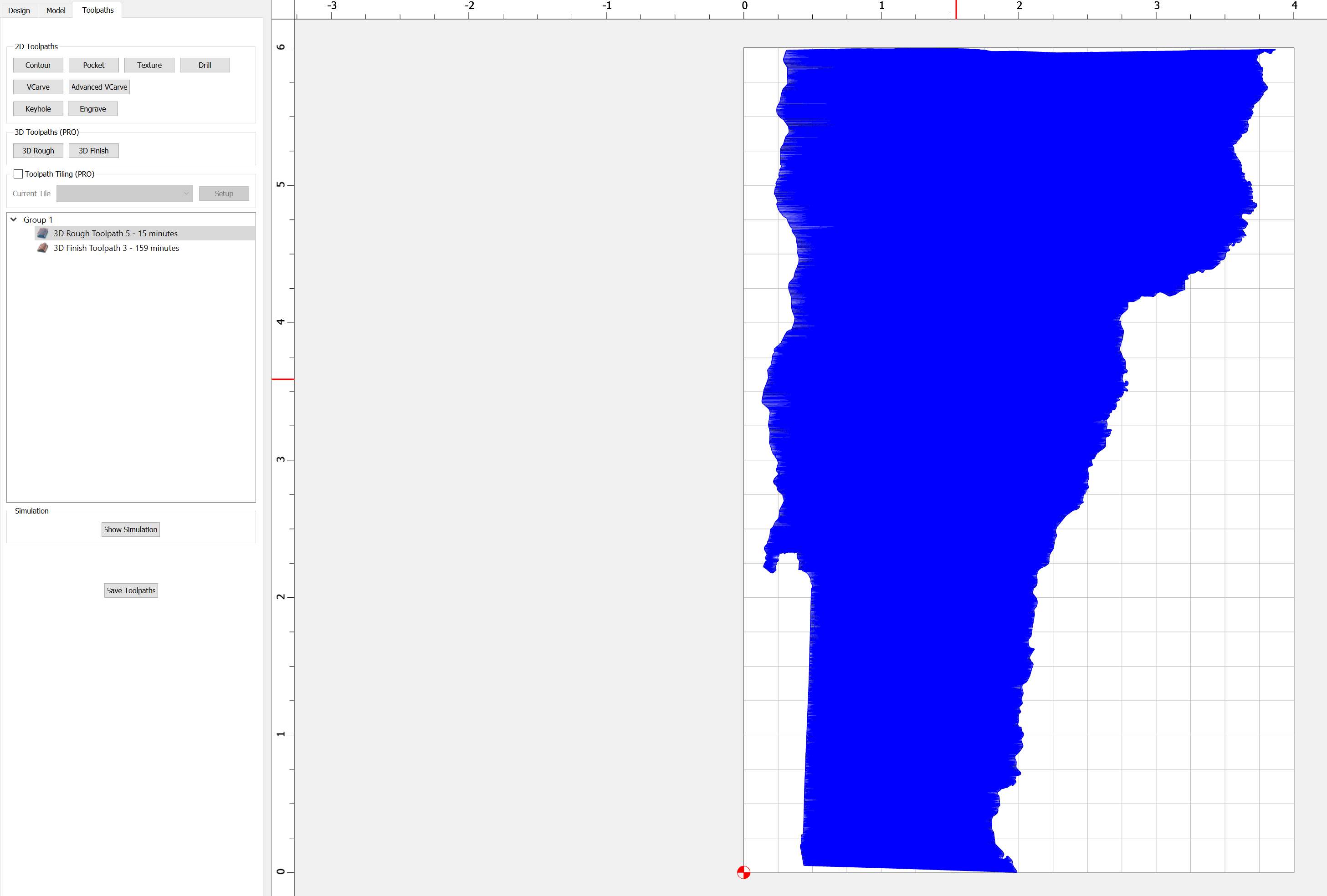
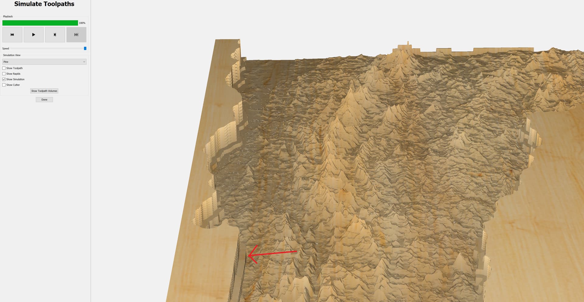
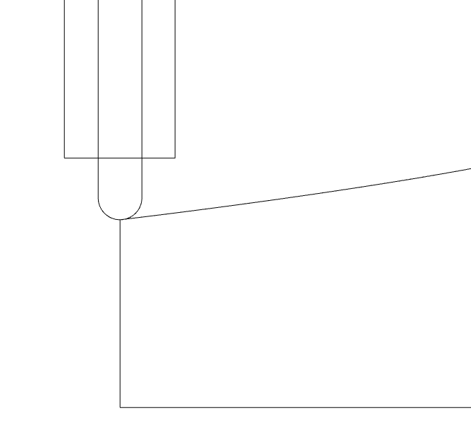
I’m very new to 3D toolpathing but consistently running into a weird issue. I created a 3D rough toolpath using a 1/8" endmill selecting my 3d object (topographical map of Vermont), then selected the same 3d object for a finish toolpath using a 1/32" endmill. The simulated result is leaving a significant “shelf” around the perimeter of the cut out, any ideas what’s going on?
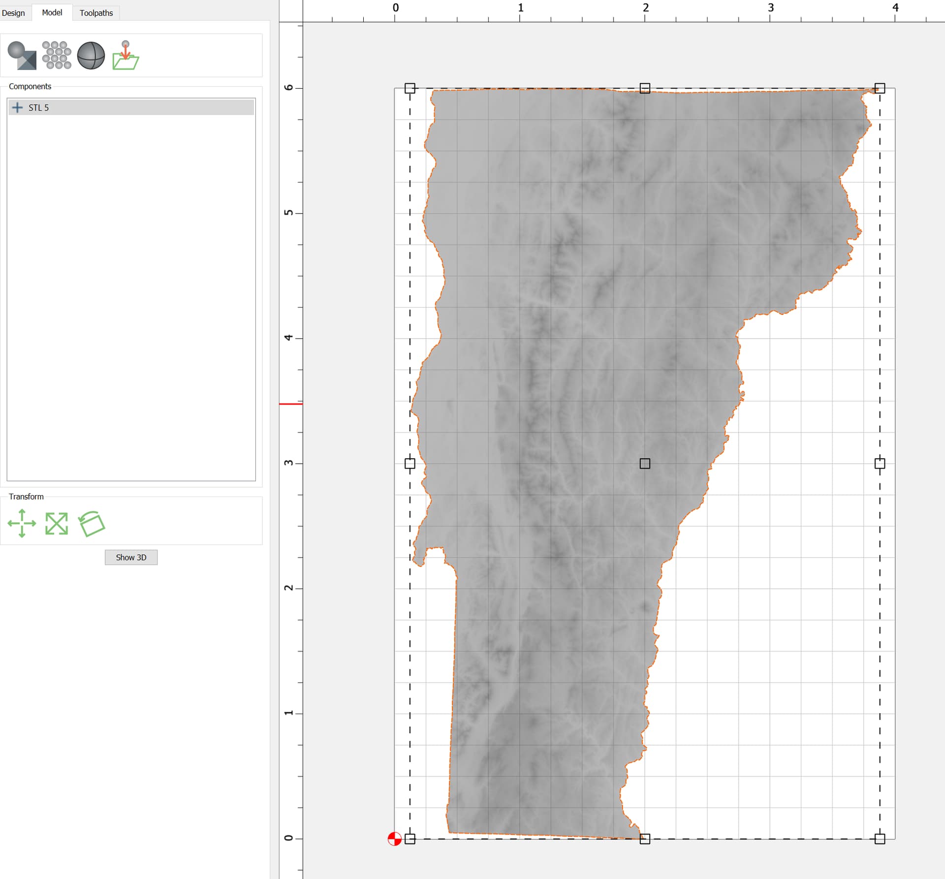
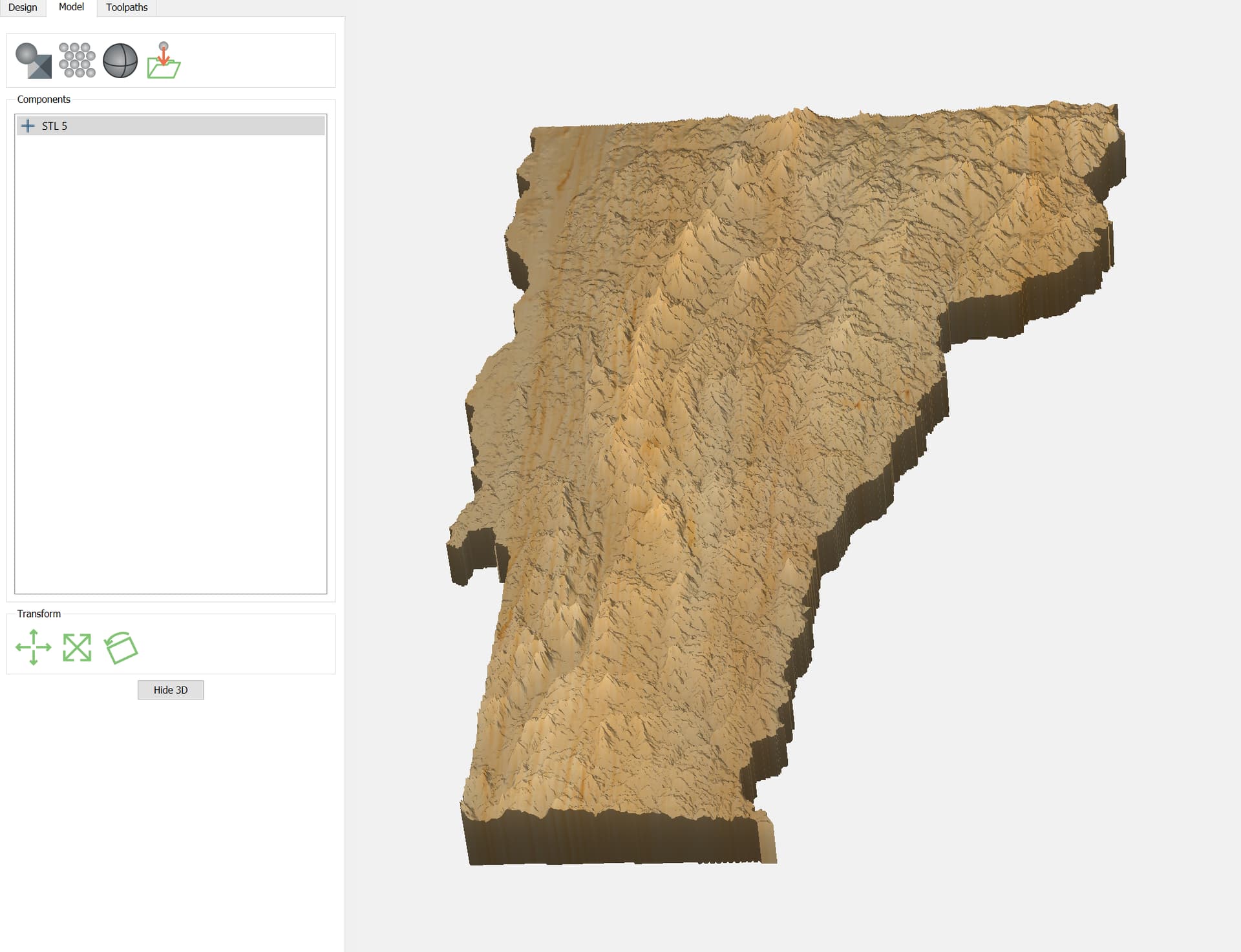
What does it look like in the modeling tab?
I really want the map to be inset into the wood because I’m going to fill it with resin
Ah, I think I know what’s happening. You’re using a larger tool for roughing, right?
3D toolpaths have an “on” condition for the boundary, meaning the center point of the tool will be over the boundary, if it can get there.
You can either create an additional 3D component to look like the model you want, or use separate offsets for the rough & finish tool.
1 Like
Ahhh that makes so much sense! I will mess around with the offsets to see if I can get them to match, really appreciate the quick help.
This topic was automatically closed 30 days after the last reply. New replies are no longer allowed.