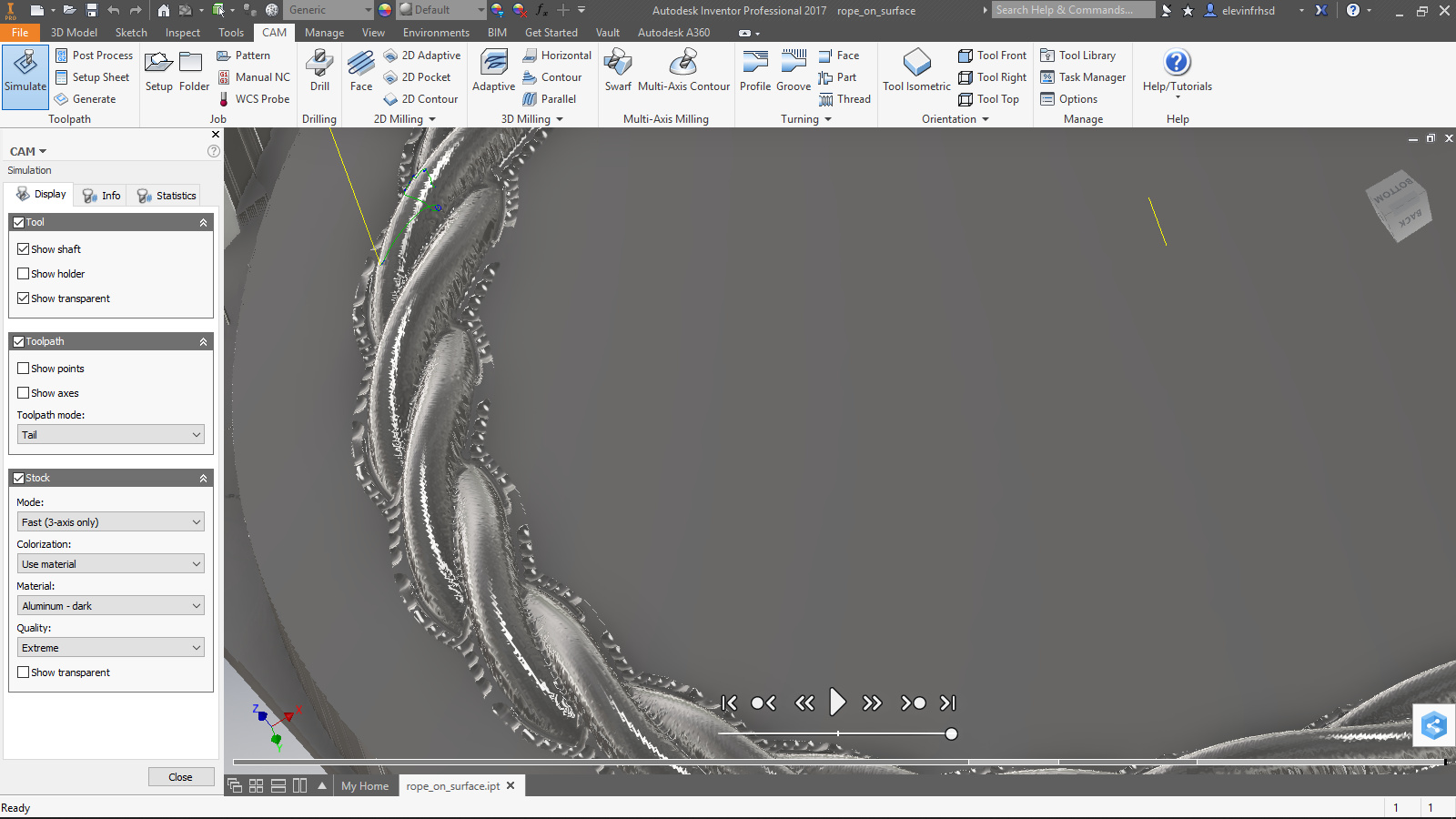
And now to the CAM aspect:
I planned this around tools I have on hand and the capabilities and envelope of the Nomad and tried different strategies until I found one that gives a good product. Not quite the same set I described last month, but similar. There are other ways.
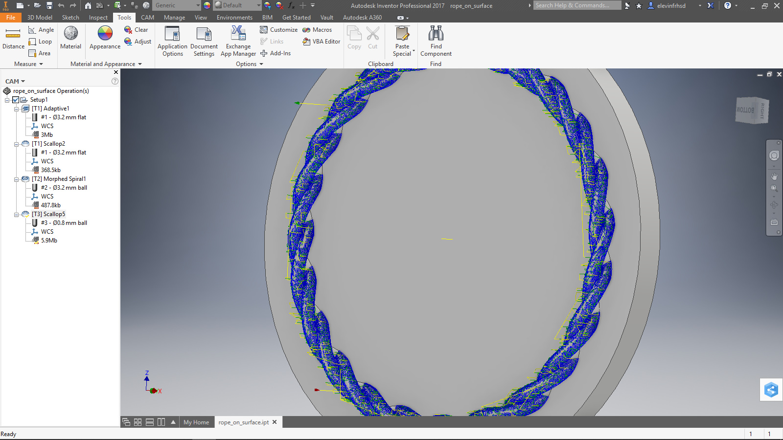
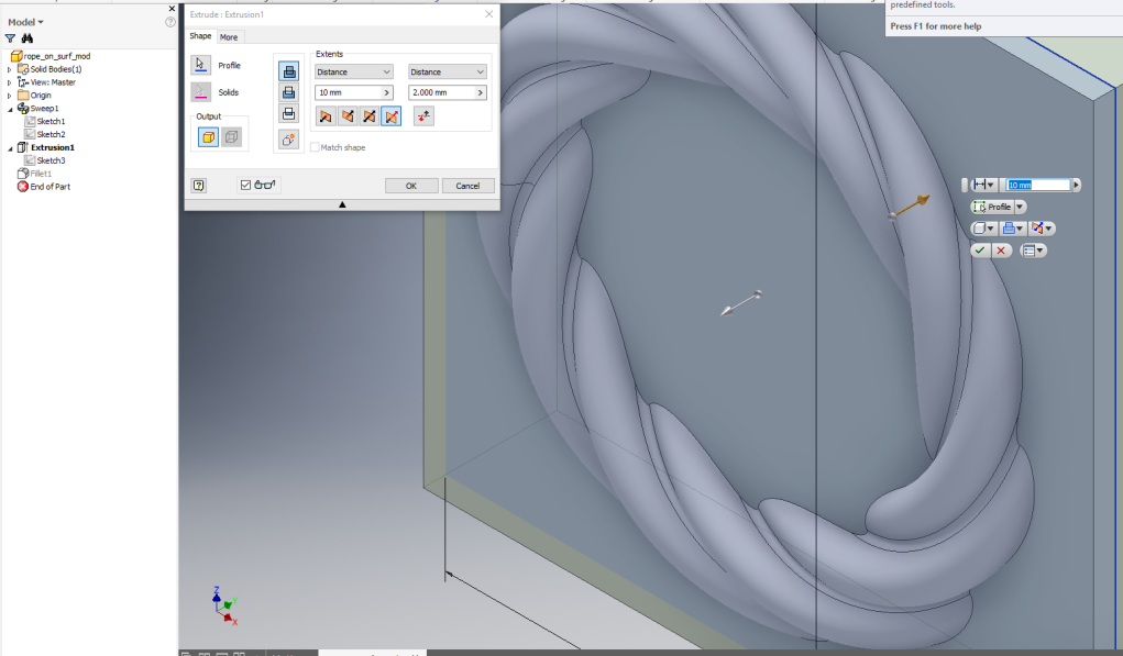
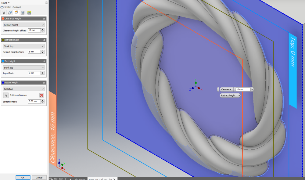
Four operations were used. The first two use a 1/8" (3.175mm)m square end endmill to rough out the whole part and then surface the base. Speeds and feeds were 10KRPM and 1m/min (defaults I use for this tool… sufficient for most wood and plastics on the Nomad). I didn’t bother doing anything with the heights except for the bottom height since there is plenty of room for this part and I wasn’t worried about a little wasted motion. The bottom height was set to the TOP surface of the base (minus an epsilon of 0.01mm) to prevent the path planner from trying to machine the outer boundary of the stock.
This is key in a lot of jobs. This is the easiest way to avoid hitting clamps, wasting time and tool removing material that can or should stay, and so on. Here, it meant I needn’t worry about the clamping being hit or exact sizing of the stock.
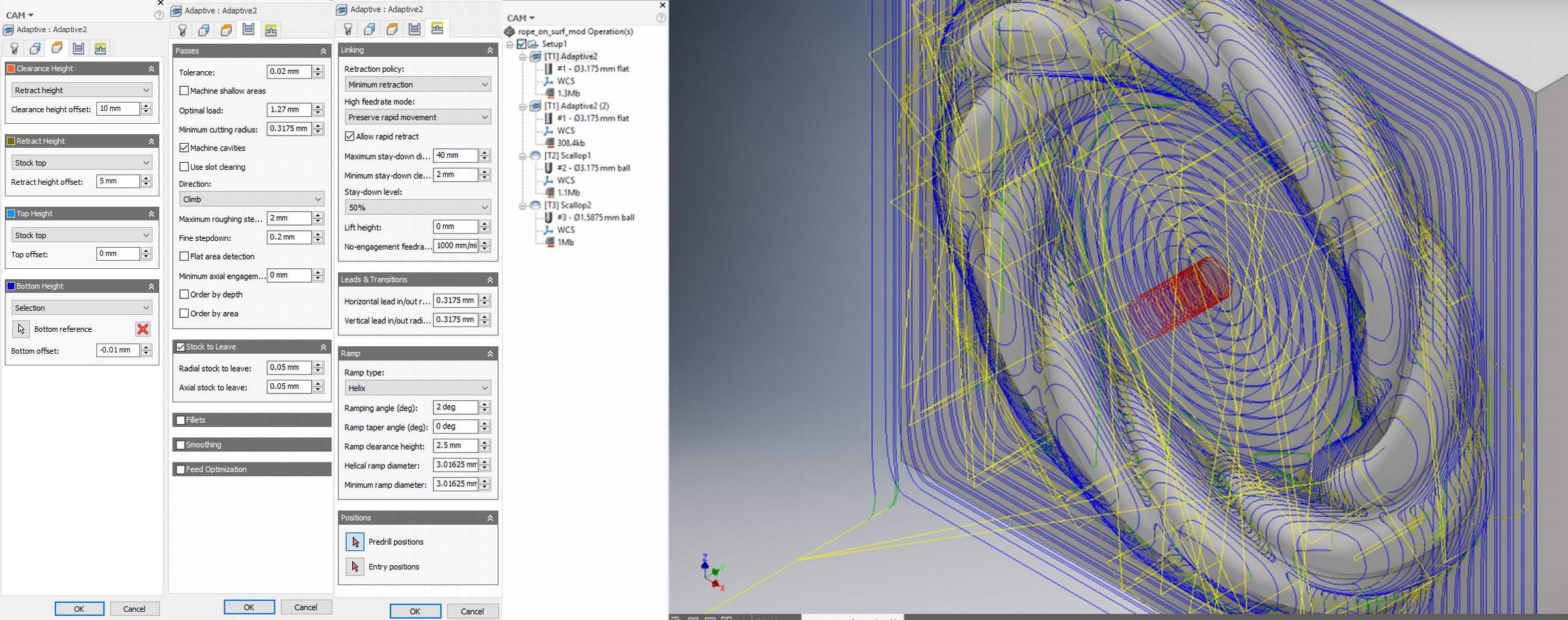
On this small part, I set the tolerance to 0.02mm (could have left is 0.1mm for roughing, but in this case it is minimal difference in file size or path generation). Fine stepdown is at 0.2mm and I had it leave 0.05mm for finishing. This means there is AT LEAST 0.05mm on all surfaces, but over 0.3mm on parts the sloped surfaces, due to the stairstepping.
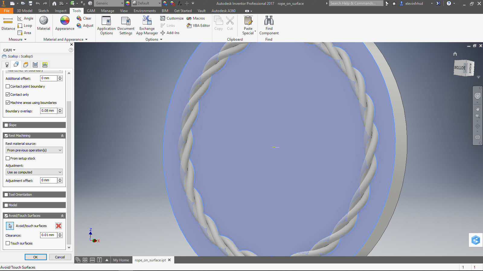
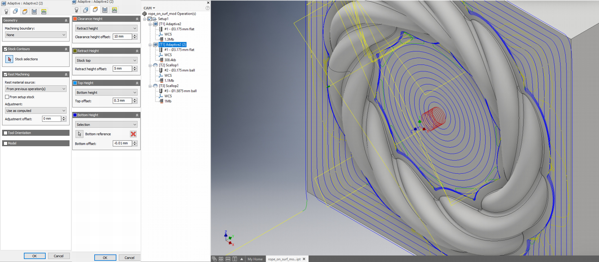
Next I surfaced the base. Another adaptive, and I used the bottom and top heights to keep the operation where I wanted. Also note the selection of rest machining. This lets the planner know this follows the other operations, so it won’t cut air to get to the surface. I didn’t bother changing the helical entry setting. 10seconds isn’t a big deal, and it is fun to watch.
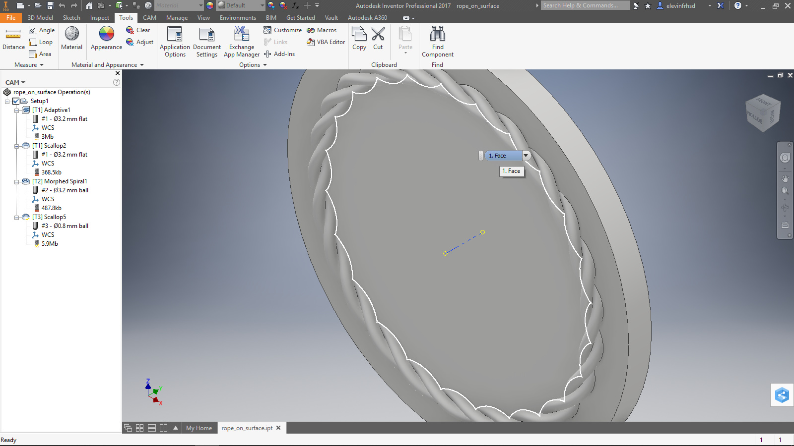
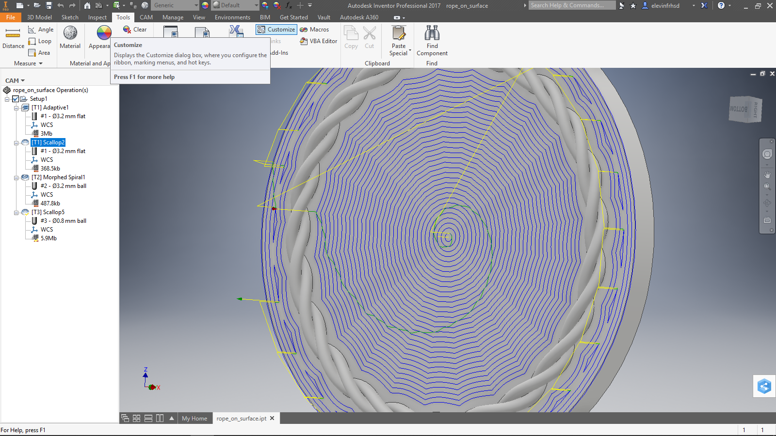
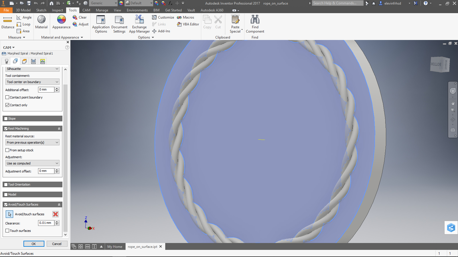
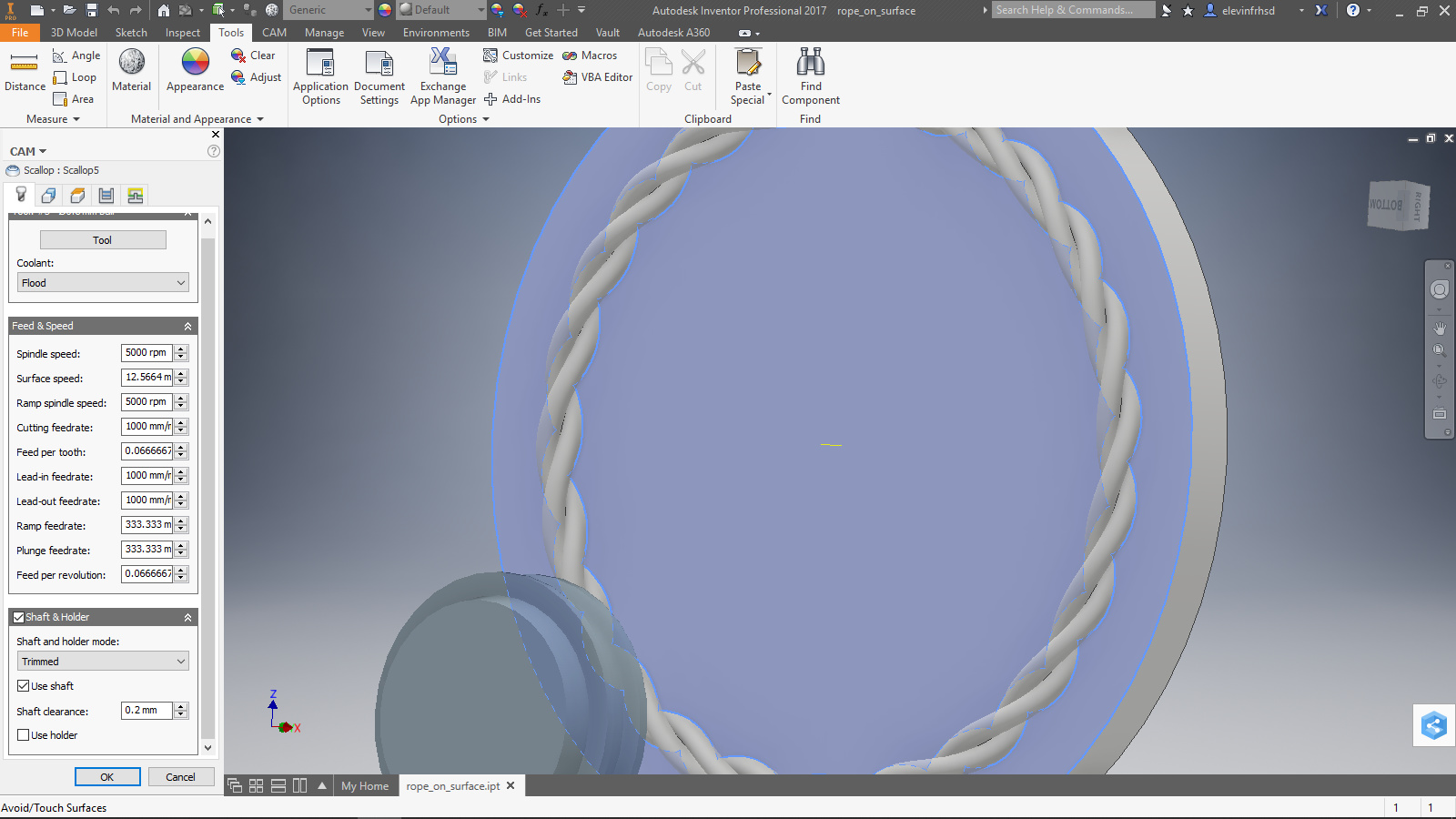
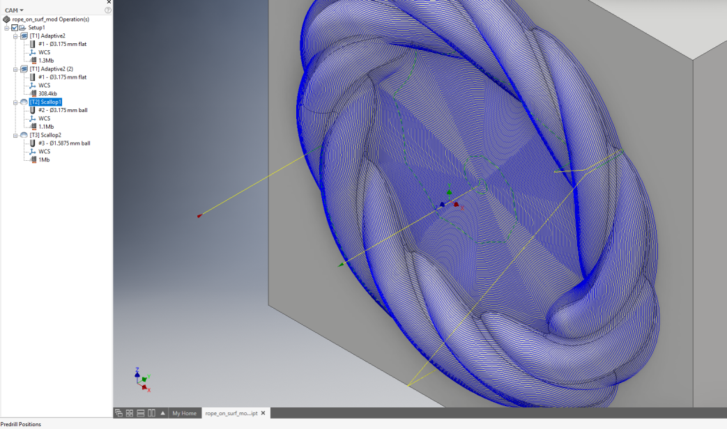
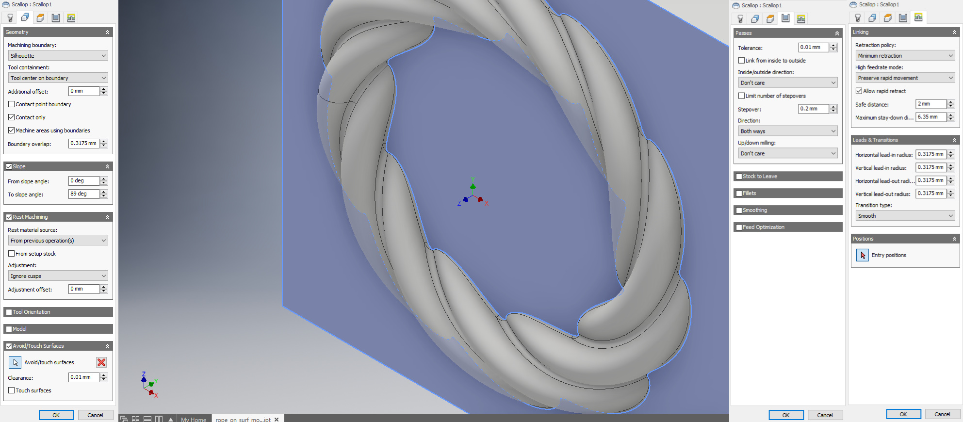
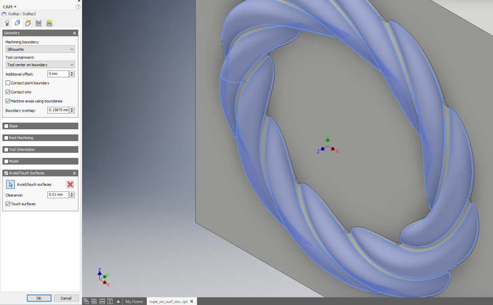
The next tool: 1/8" (3.175mm) ball end for first finishing on the raised surface
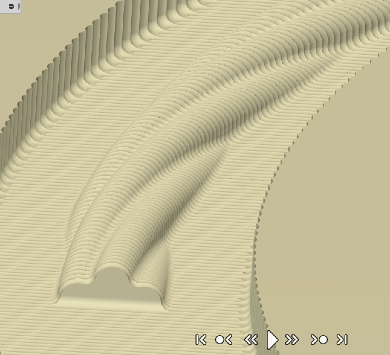
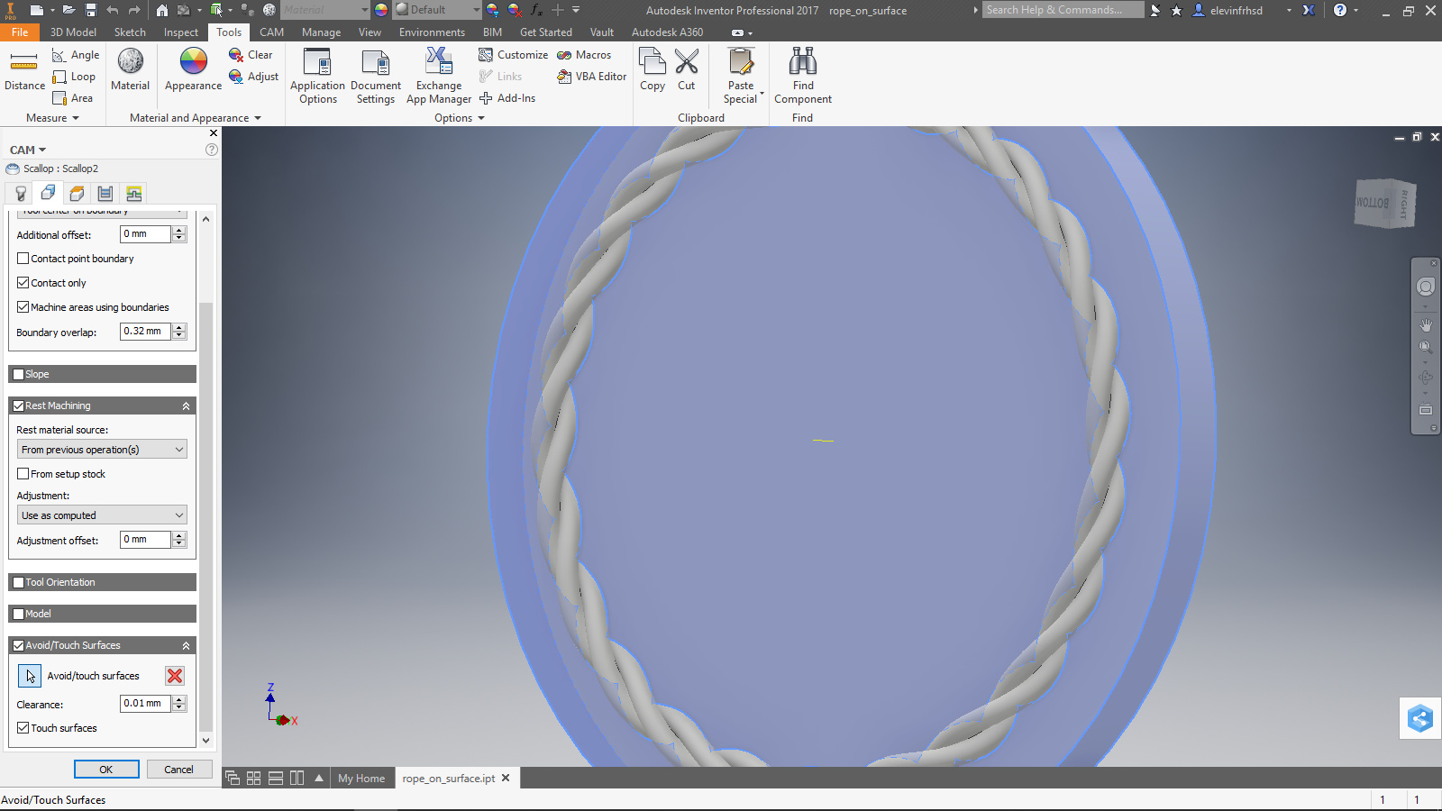
The scallop tool tries to keep uniform stepover relative to the surface tangent, rather than the X-Y plane. I didn’t remove the already surfaced portion in the middle (careless… ) because I neglected to set the bottom height properly and the avoid doesn’t always do it. No one at AD seems to be able to tell me WHY the avoid doesn’t always do it, but…
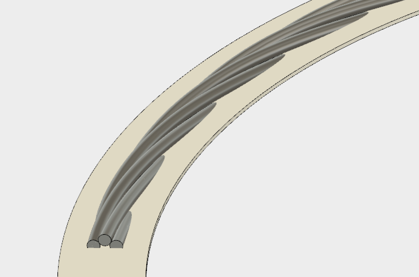
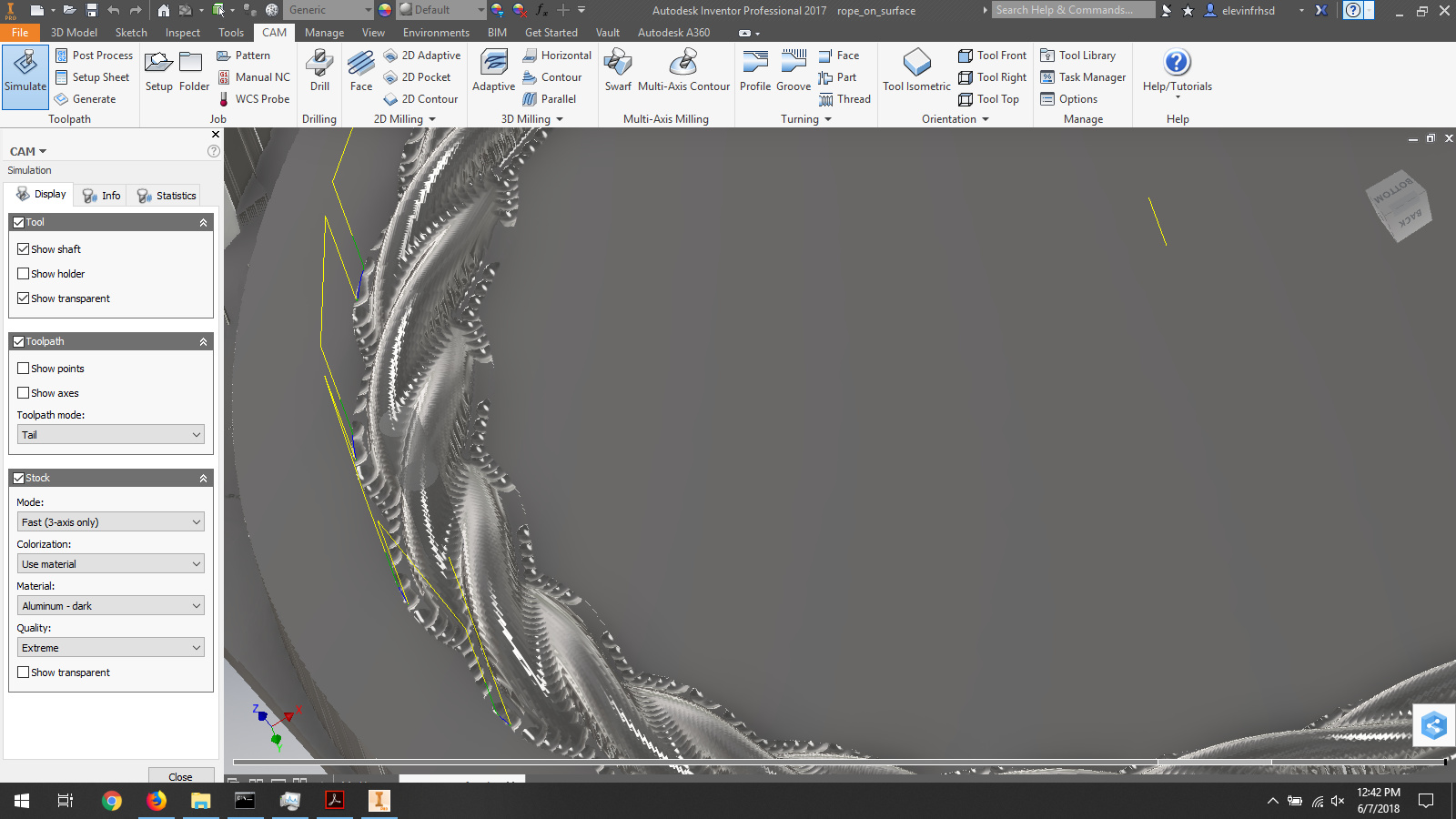
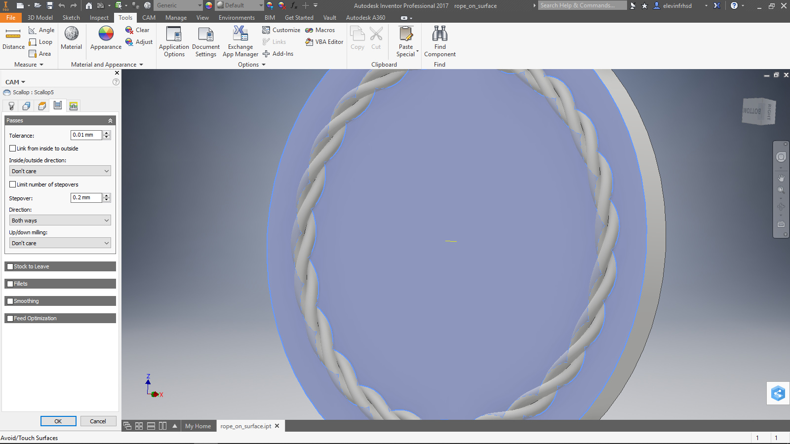
As you can see, the surface in the middle was specified for avoidance. The tool did not touch, but the machine did cut air in that section. Note the stepover is ball-end diameter/16. This gives good results with little scalloping on the convex surface. (Scalloping on a convex or concave surface can be interesting to compensate…) The tool does not make it deep into the fillet between strands or all of the way to the bottom, but at this stage, the product is pretty good
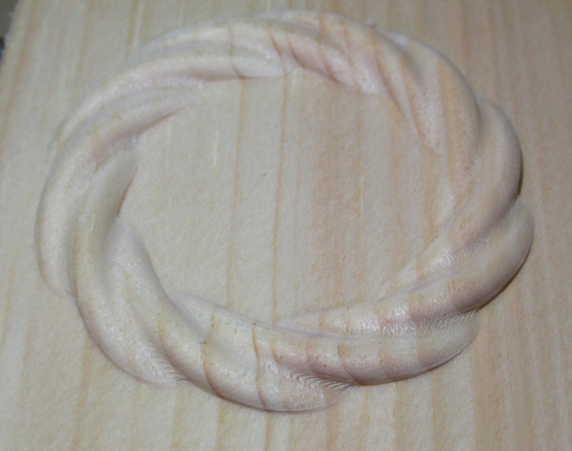
You can see where the ball end did not blend the surface near the base (there is a sharp edge and lip where vertical meets in, especially visible on the edge closest to the camera)
You can also see a bit of tearout in the grooves between the strands, since the ball end is effectively buried.
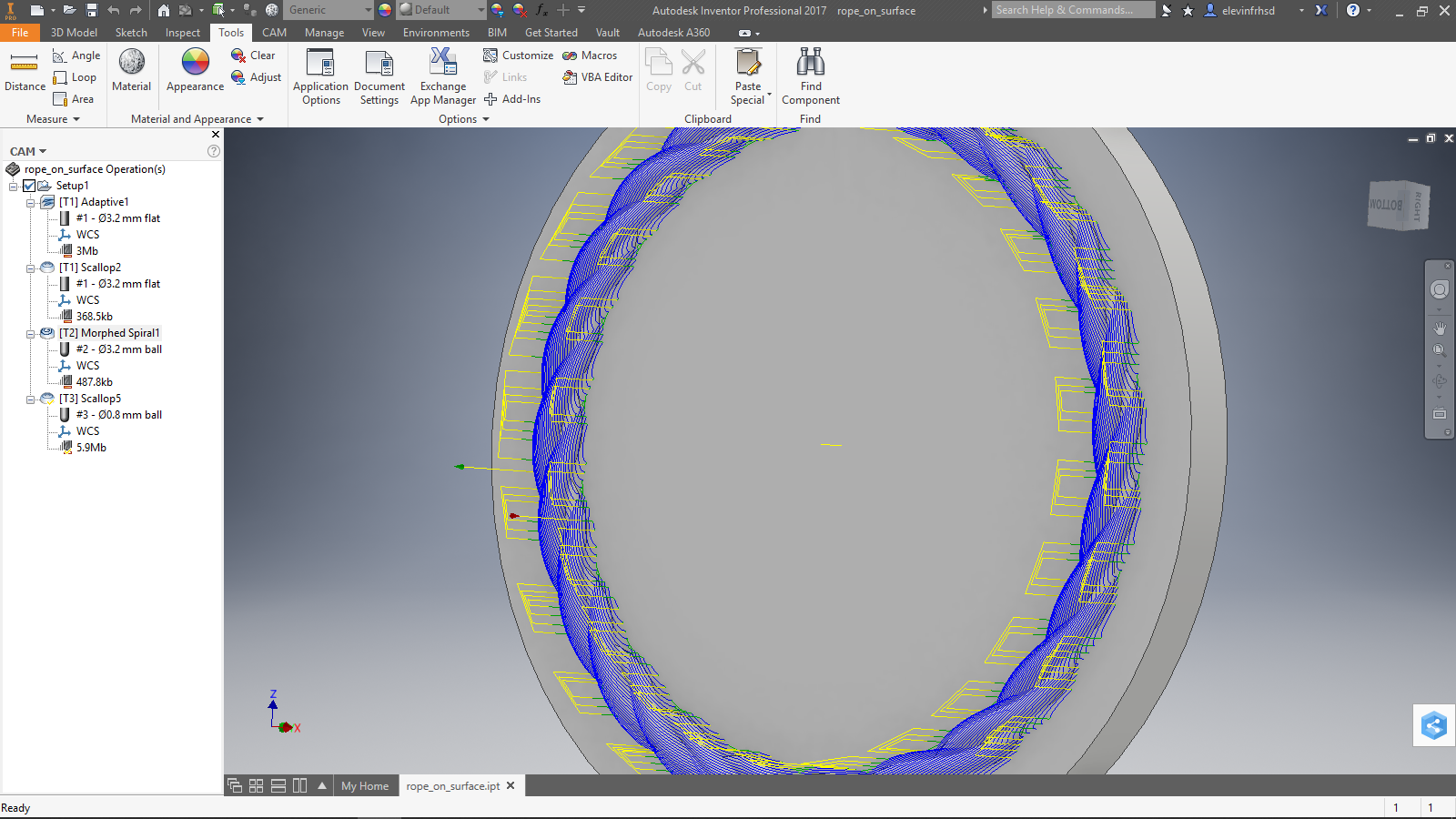
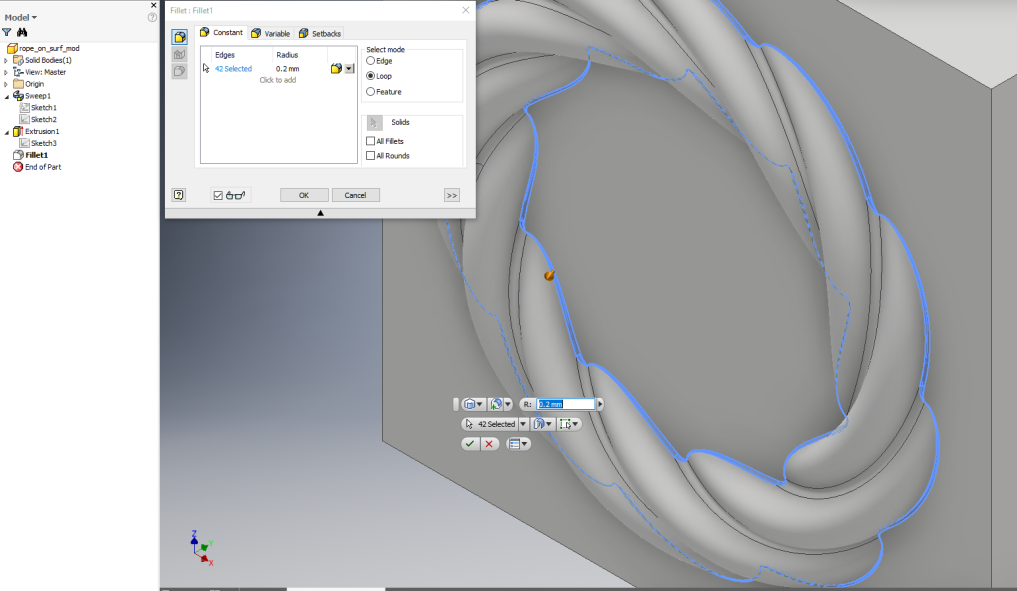
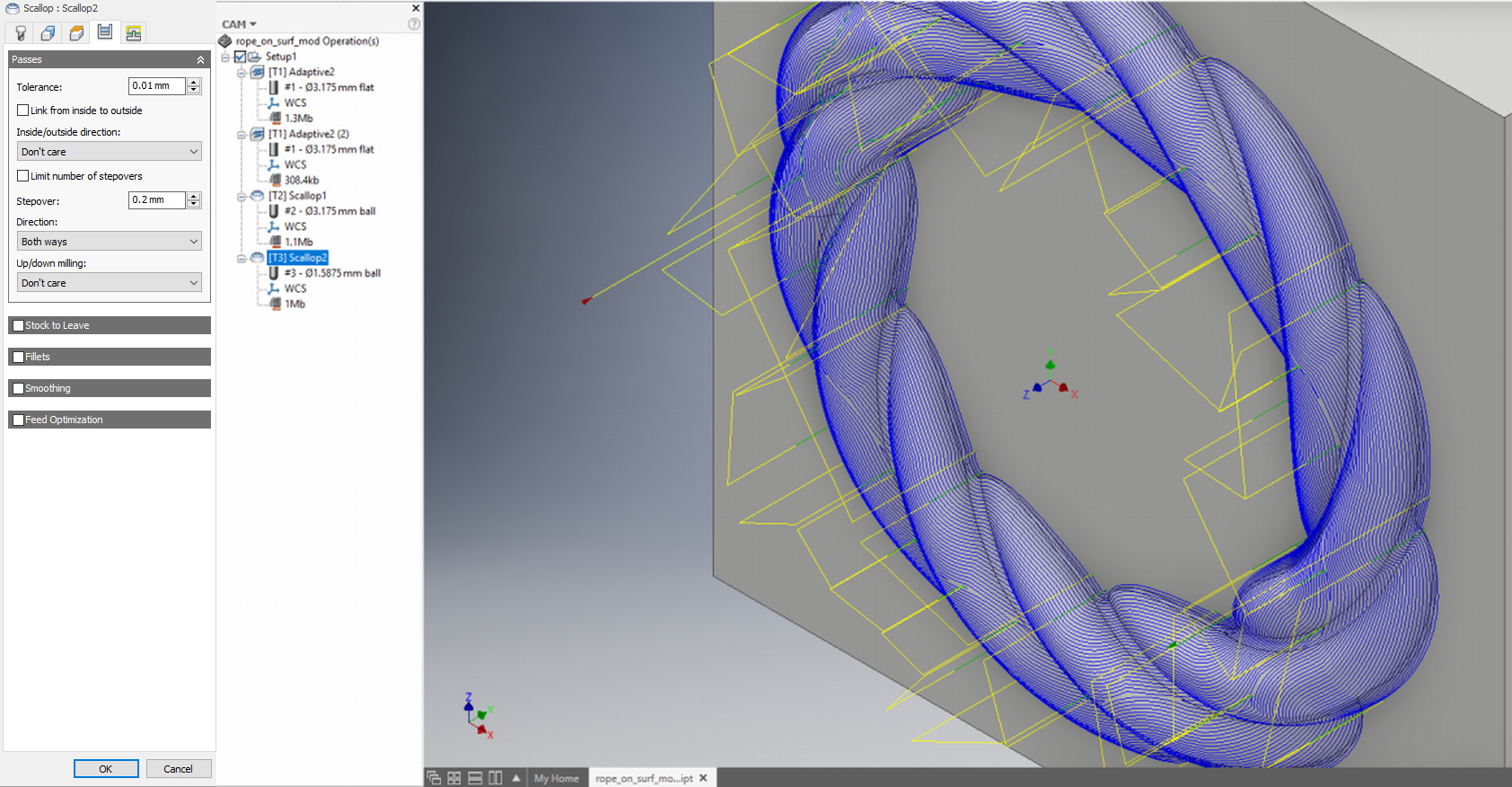
This is handled with the last tool: 1.6mm ball end. (this time I properly set the bottom height)
I used the 1/8 diameter here. The surface looks flatter to the smaller tool, and the primary point is to clean up what the larger tool couldn’t reach. There are two ways to go about this: one is enable rest machining, the other is let it hit everything.
I let it do the whole thing again. Rest machining actually takes longer here and generates a much more involved path, as it is a whole ton of small cuts in odd orientations. Longer to generate, longer to run, and more g-code. In this case, I specified the surfaces the tool should touch, and also properly set the bottom height.
Note that I DID NOT have the tool touch in the grooves. The tool nose radius is larger then the radius in the groove. It won’t get there anyway. If I finished with a smaller tool, I could bring the radius down a little more, but why? That would be a lot more time and not be as clean, and those tiny tools are pricey and break easily. The other item is, if you are using the tool nose radius, why bother putting the filet in the model? Well, that has to do with the tool path generator. If the surfaces come together in the groove (no fillet) then things get weird where the edge meets the base, and peck marks show up. Having the constraint be the two convex surfaces at either side on the groove keeps that from happening. Again, no one seems to know why this happens, but I have run across it a couple times, and now I know.
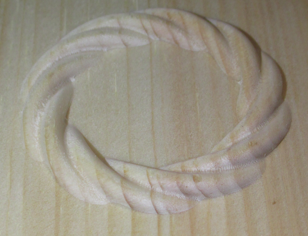
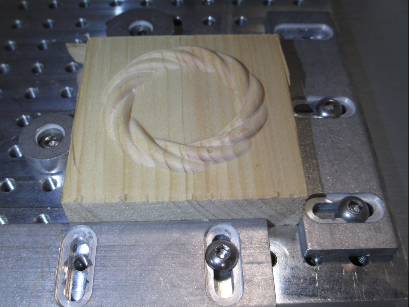
The final product came out pretty good. This is still in the machine, but I vacuumed and hit it with a toothbrush to get the fine dust.
You can see that the ledge at the meet with the base is faired out pretty well. What looks like tool marks in the grooves is partly the wood grain. The tool marks are not visible to the naked eye. The whole piece is 50mm diameter.
For reference, the workholding was with cams on a bed of holes: