I have a Shapeoko 5 Pro and use version 8 of Carbide Create Pro.
I am interested in carving a 3D shark sculpture from a block of wood using a STL file of the shark, but do not fully understand the limitations of the CNC.
In other words, can I carve the top of the shark and then flip the stock and carve the bottom of the shark? If so, do I need to find a STL file that does not require any cutting that cannot be accomplished from a top or bottom perspective? For example, the teeth of the shark would not be able to be cut from a top/bottom perspective.
So, I am interested in learning the limitations of the CNC for 3D sculptures, i.e.,
What is the maximum height of the block of wood that I can use?
What cannot be cut from a top/bottom perspective?
Can anyone point me to a STL file that could be used?
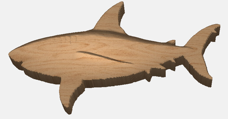
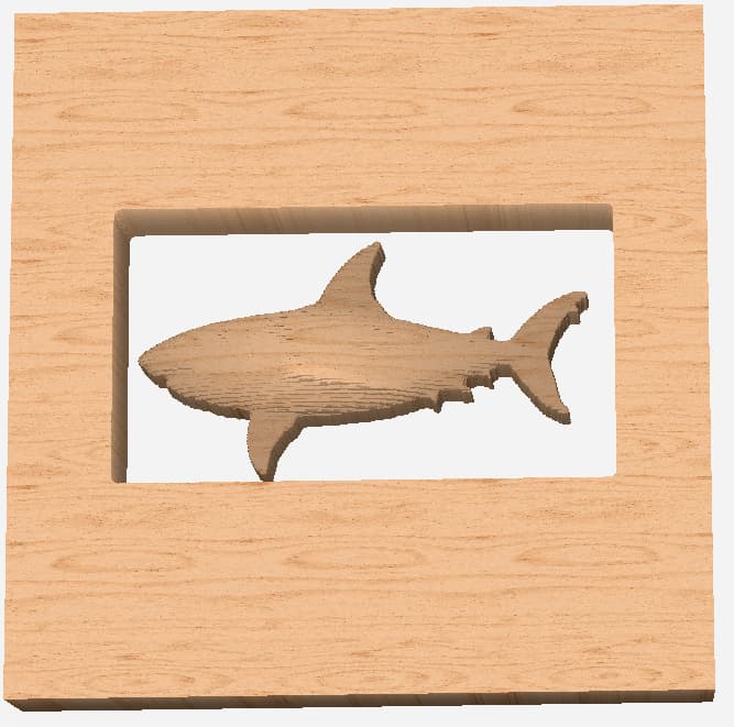
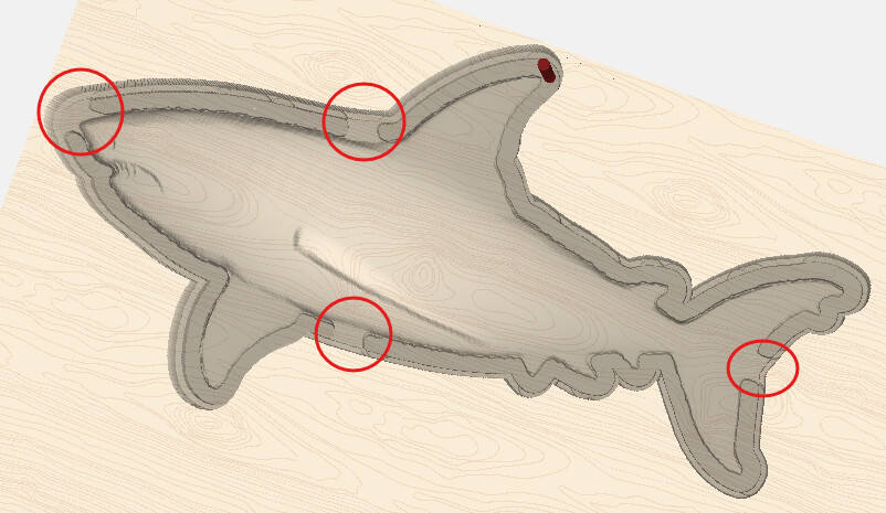
I am attaching a picture of the type of 3D sculpture that I would like to make.
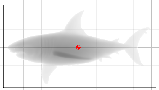
QUESTION 2: Why does the immediate area around the shark appear totally cut through? Shouldn’t I have a 1" base that will be used to carve the flip side?
After flipping the workpiece (and maintaining xy positioning with dowels), I intend to carve the other side (Side B) of the shark to a height of 1" and a base height of 1" as well. (I am using a STL file that mirrored the first side using Blender.)
QUESTION 3: Even using dowels to maintain the correct x,y position of the shark, how do I hold down the non-flat side against the spoilboard so that the workpiece does not move when Side B is being carved? Is there any way to have large tabs holding the sculpture to a frame or border?
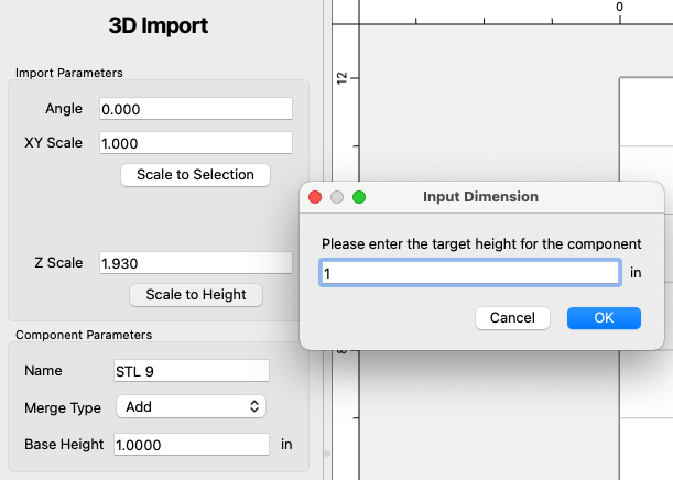
Assuming the final width of the shark will be 2", then you want to import it at 2" height.
Then make a 1" - radius of cutter base and use the Max merge type. The base should be a bit larger than the shark so it stops the cutter from going all the way through.
Then on the flip side, do the same thing with the STL reversed.
You may want to model tabs to hold it in place for the flip side cut.
This all assumes the parting line is right at 1". If the shark is on a bit of an angle then the base for the first cut will need to be lower.
If you want to share the STL and your sizes, we can show you how to set it up.
OK, so the raw STLs are 7.835" x 4.0818" x 0.5182"
They do have a flat parting line, so you’re good there.
The whole thing, both sides together look kinda skinny
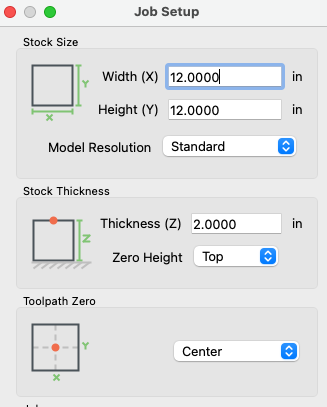
You want to import them at 8.35" x 4.5" x 1" each?
I would do it this way. Start with a workpiece a little bigger. Say 9 x 5
Make a 9 x 5 rectangle for the base.
Make a rectangle your 8.35 x 4.5 and make a full size base & import the STL at 1" height
Create a base component 0.875 thick, and import the STL at 1" with a 0.125" base.
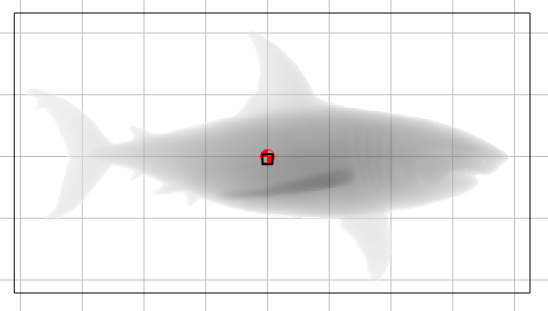
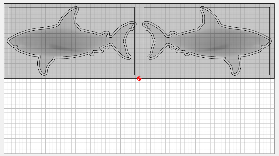
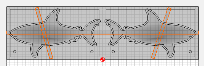
In this one I used a 18 x 10 workpiece, a 18 x 5 base, and two 8.35 x 4.5 rectangles to import the STL. With the zero in the center I can use the same physical corner for my XY zero when I flip it. And I can program the toolpaths in the same part.
Thank you very much for the input. As a relative newbie to the 3D modeling world, I want to ask you some questions so that I can understand the details better.
I totally agree that the width of the finished shark is too skinny at 2". I was using that dimension as “proof of concept”. In reality, I would want the width to be 4" to 6". Also, where did you get the raw STL dimensions? Are you using a 3D modeling program to analyze the STL file?
In your .c2d file, you include both sides of the shark. Wouldn’t you want one shark side per file so the flip side is positioned at the same location?
It looks like you put a border AND an offset around the shark. I have used offsets, but have never put an offset around an STL image. How did you do that?
Your modeling includes “tabs”, but when I run your tool paths, I don’t see them. Can you give me more detail on the tab tool paths?
I haven’t found a good explanation of the use of 3D modeling as implemented by Carbide Create. Have they produced anything? If not, where would I go to understand the use of the various components?
I really appreciate your advice. Sorry for the newbie questions.
I think 2" is plenty, since the side fins are not sticking out. The raw width of 1.0364 seemed a bit skinny to me, but in the file I scaled up the width of each half to 1" for a total of 2".
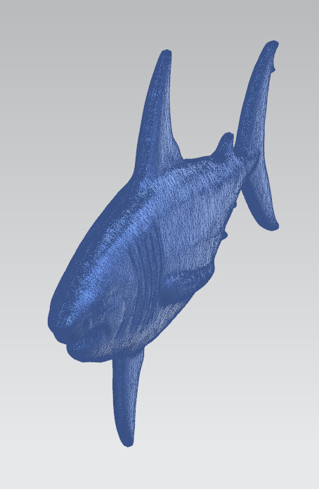
I imported the STLs into NX, then rotated the left side around to put them together. They import at nominal size, then you can scale them if you want.
You can do it in separate files with the zero at lower left on both. You have to be very conscientious with your flip. The way I layed it out, you cut the right side with a lower left zero to a known square corner. When you flip it left → right, that physical corner on the stock is now in the lower right. If you zero from the same physical corner, and your stock is aligned & square, the alignment should be very close.
After you add the components for the shark, right-click on the component and “Create Outline Vectors”. Leave the value at 0 and it will trace the bottom of that vector. Then you can offset that vector to get your 3D toolpath boundary.
For a 3D model, I added the tabs as part of the model. The height is 1.125, and the centerline is at 1", so the overall height of the tab from both sides is 0.250"
Many thanks to @Tod1d and @WillAdams for their assistance in answering my never-ending questions. I have a lot to absorb and try today based on their advice.
I imported an STL image of a shark into the MODEL tab of Carbide Create Pro v8 using the Top orientation (let’s assume you are looking at the side of the shark with nose pointing left). When I flip the workpiece in order to carve the other side of the shark with nose pointing right, can I re-import the STL file and then select another orientation (Bottom) and then change the angle until the image is correct (in the MODEL tab)?
Or, is there a way to mirror a STL image in CC Pro?
Or, do I have to mirror the original image in Blender and then import a fresh copy of the STL into Carbide Create Pro?
You have both the left & right STL, which appear to be mirror images.
There is no way to mirror in CC, so you’d have to do it in another software.
If the left & right were joined into a single solid, then you would use the bottom view for the other side.