3D Modeling View and Tool Path Rough Simulator Different

Test.c2d (2.2 MB)

Hi All,
I have two modeling components (Outline and Inside). After I Create them I view them in the 3-D modeling view and I can see both of them. When I go to Tool-Path and select them and do a 3D rough and view them in simulator I only see the outline. I can create separate tool path but when I try to select both only the outline shows.
Any Ideas what might be causing this?

Thanks John

Hi @John3,

To me everything looks as it should: the 3D roughing op is using a 1/8" endmill that is too big to cut the small “inside” features, so it doesn’t, and nothing shows inside the outline.

For the sake of testing I tried generating a 3D finishing toolpath with a smaller (1/32") endmill and the result is then as expected:

1 Like

Julien,
I would have never guess. My total time is 33 hours with Feed Rate - 1524mm and Plunge Rate - 1016mm. What where your parameters to get it to run a more manageable time?

I did not pay attention to that at all, I just picked the 1/32" tool under Nomad/MDF and kept the predefined values. I’m not near my computer right now and it’s getting late here, I’ll check tomorrow (or someone else can chime in!). You could alternatively use a Vbit to get inside those small features.

Side note: since this model is essentially 2D, it may be simpler to just use 2D toolpaths. It would not change a thing to the tool size constraint though

1 Like

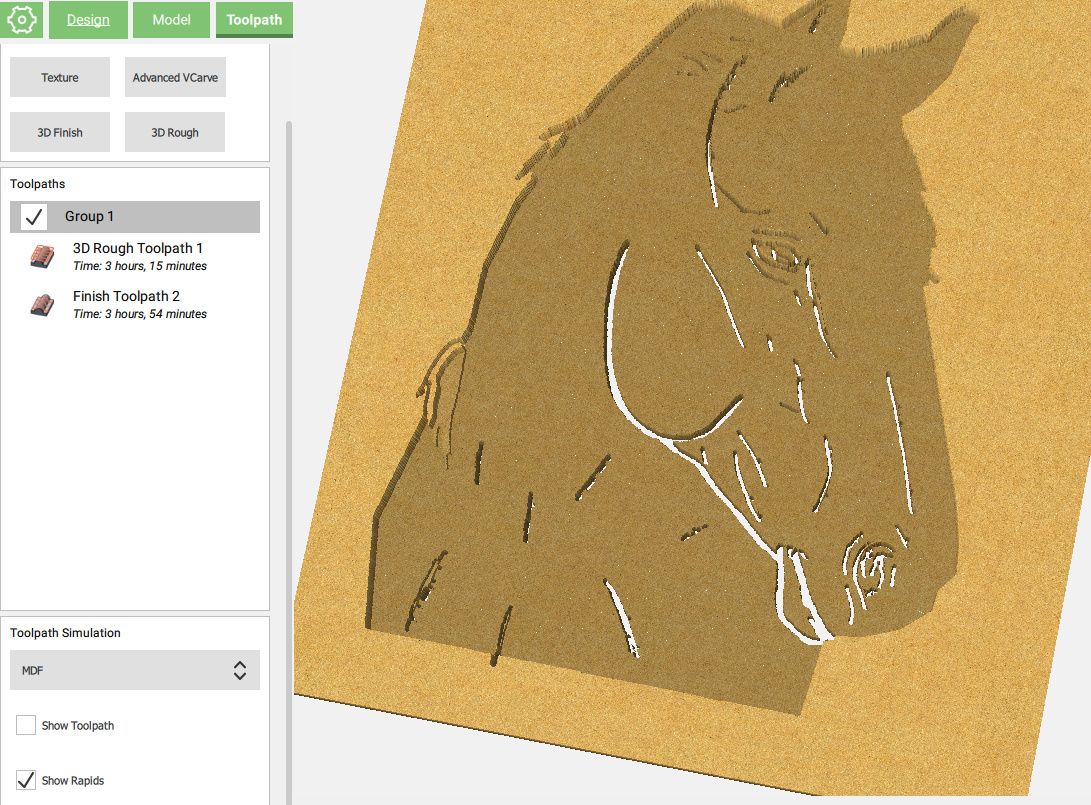
So if you do want to do this as a 3d job, the ballpark times e.g. for MDF could be:

Roughing with 1/8" #102 / default MDF settings

image

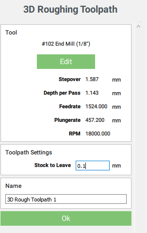
Note that I set 0.1mm stock to leave (it won’t take 0.0), because in this particularly flat design, there is no real added value to using a large stock to leave.

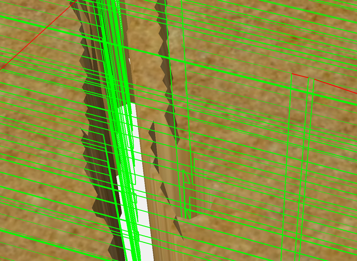
Now for the finishing toolpath, there is a problem: the quick & dirty test I did in my first answer selecting a #122 only SEEMS to work because of a bug in the toolpath generation, that has the tool plunge all the way to the bottom of the stock near edges of the features:

So while the preview looks ok that would end-up very badly for the cutter, the #122 only has a cutting length of 0.0625" (1.6mm) and in this scenario it could plunge down 10mm deep in one go, most certainly leading to a collision between the endmill’s larger shaft and the material.

Side note: I suppose your 33hours estimation is either due to a wrong (too small) depth per pass during roughing, or too small stepover, or just a bug in the estimated time (it was reported to happen), because selecting the default settings

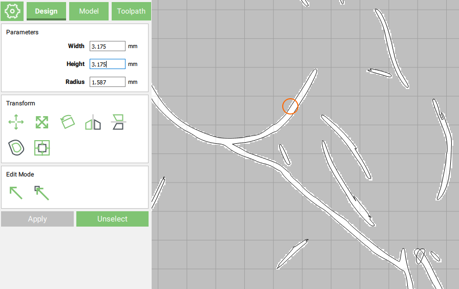
So I got carried away and played with your file a bit, changed the inside features to not cut all the way through,

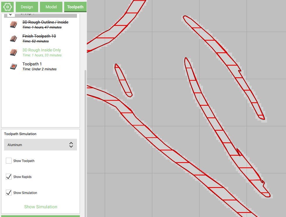
  1. I added a first contour toolpath with #102 that is there to clear some extra material outside the outline, such that there is no collision when the time comes for running the finishing pass with the 1/32" endmill and its 1/8" shaft plunging deep
  2. 3D roughing using #102 at default MDF feeds and speeds (18000RPM & 1524mm/min), 0.1mm stock to leave
  3. 3D finishing with #122 and 0.3mm stepover, 10000RPM, 1524mm/min

which brings total time to less than 3 hours. In MDF, that is, you may want to adjust if cutting harder material.

Anyway, hopefully this illustrates a few things you may want to look into for your project, you could also redo do it as a roughing pocket + Vcarve

Here’s the modified file testCHEVAL3.c2d (2.2 MB) if you want to have a look

2 Likes

I have to say your support is absolutely incredible. Top-notch. Give me some time to review and digest. John

2 Likes

First of all thank you again for taking the time to review my image.

I did not realize that there are speed differences between Nomad and Shapeoko. Up to now there wasn’t a problem 2D but when you get into 3-D it’s a whole new ballgame. This is probably intuitive to you but now that you pointed it out I can use these default instead of changing them manually, but it is a learning process.

As far as your initial conclusion I was curious on how you determined that it was related to a bit size. I however think that the cause of not displaying the Inside image in Tool Path somehow needs to be identified to let the end-user know why it is not being generated. As previous noted if you generate these images Outside/Inside separately they work, still having issues understanding as to why when combined they do not work.

Thanks John

Hi @John3,

It’s one of those things that you learn as you go, usually you notice it immediately because the selected endmill is small enough to go in some of the selected features, and not others, and you see a “partial” toolpath.

In a simpler case of, say, trying to cut a rectangular pocket that would narrower than 1/8", with a 1/8" endmill, CC would display that it is an “empty toolpath”, as a hint that something is wrong.

In your case, since you select both the large outline AND the small inside features, and try to generate a toolpath with a 1/8" endmill, CC tries and go “wherever it can” within that selection with that endmill: in your case, it goes everywhere except inside those small features, so technically it’s not an empty toolpath, and you get no specific message.

It could be helpful to have CC give you a warning that it was not able to go inside all selected features, but there are cases where it would produce a warning while this was done on purpose by the user, so it would become annoying to get false warnings. Even the big shots (Autodesk/Fusion360) are not good at providing helpful hints when their toolpath generation does not produce the results the user expected.

Anyway, a simple thing you can do when in doubt, is draw a circle the size of your selected endmill, and move it over the features: you will see immediately whether it’s small enough or not:

Can you detail the part about how it works when you generate the inside separately ? I was not able to reproduce that result, but I may be misunderstanding the steps you took.

1 Like

That is such a great idea you should include it in with tips and tricks. As far as getting different result in Tool Path Rough. When I select Outline / Inside and generate the Tool Path. When view with simulator I do not see the inside. I disabled this tool path deselected and Outline. At this point only the Inside is highlighted. I regenerate the Toolpath for Inside only, now I can see the Inside . Not a big deal but I would expect the same results. See attached file.
Thanks John
TestA.c2d (2.2 MB)

1 Like

Hi @John3,

I checked your file, you are right, and it’s basically a corner case of the toolpath generation logic.
When selecting the inside features only (which are all too small for a 1/8" endmill), the behavior of 3D toolpaths on edges shows: it generates a toolpath that goes right to the edges of the selected features, regardless of the diameter of the endmill:

At first glance this may seem like it’s what you wanted, but those areas are then more than twice as large as they should be. I added a small 1/8" circular pocket in the simulation below to illustrate:

I guess when selecting both outline and inline, the toolpath generation logic sees those features as “internal” edges and behaves a bit differently.

Bottom line, you should probably use 2D toolpaths (and a smaller endmill) to cut these inside parts, or switch to a V-carve approach.

As indicated previously this is just an exercise for me to learn 3-D. I don’t mean to chew up your bandwidth, as you been very responsive but I bring these things to your attention as they may be bugs. I’m OK either way I don’t necessary want to beat this horse to death, get it (he he).

Now I’m trying to put a 45° bevel as part of my 3-D drawing. I’m not even using the image, just creating a bevel. Here again i’m sure there may be other ways or better ways of doing this just bringing it to your attention as to what happens in the 3D Finish Tool Path.

The following are steps taken.

  1. I created the Stock +20

  2. I then selected the outside border and dropped it -5, with a 25° Angle.

  3. Next I selected the Inside border dropped it another -5.

  4. I then selected the Horse silhouette made it a round shape with a Scale limit height of +5.

In 3-D modeling it seems to be fine.

When I generate the rough 3-D tool path and run simulator it looks fine.

When I generate the finish 3-D tool path and run simulator it shows the inside border has raised. Any ideas?

I tried uploading it. It said that it is too large, so I’m sending the file via

Thanks again for your continuous support

John

1 Like

one thing to try… in the latest beta version (https://carbide3d.com/carbidecreate/beta/ ) a new feature was added to show 3D model parts that are higher than the stock is (a common mistake in 3d modeling) in red in the preview…

1 Like

Any chance you can compress it and retry to post it ?
I tried and reproduce your steps but I think I got it wrong. I’m happy to look at your file, to see if I can puzzle it out or maybe confirm a bug.

1 Like

Just an FYI I’m already on 467. You should have a copy I sent to your support email at 8:36 today. Let me know if you didn’t get it. Thanks!!! John

I’m afraid that Julien only works the community forums — the e-mail support queue is a different group of folks. We have your e-mail in our queue, and I linked it here, so hopefully we’ll work this out with you presently.

1 Like

Sorry, I didn’t realize that. I tried zipping in the pass but no luck. I guess I will have to do something different next time. What am I saying hopefully there won’t be a next time.
Thanks for taking the time to get the file to him.John

TestC.zip (3.7 MB)

Sorry for all the confusion. Attached is my Zip File. I finally got it to work. Thanks John

2 Likes

Hi John,

Thanks for the file, I see now how the finishing toolpath fails to cover the inner part while it should, my guess is that this is linked to how the 3D roughing toolpath was created:

Both the outside border and the inside border are selected.

Somehow the roughing toolpath is not restricted to the area between the two borders (I assume it only enforces the outer one) and roughs the whole piece, but it seems like the finishing toolpath itself, which is linked to the roughing toolpath, is contained between these two boundaries.

I tried re-creating the 3D roughing toolpath with only the outside border selected, and then re-creating the finishing toolpath, and then it behaves as expected.

It’s unclear to me what the expected behavior is in case multiple vectors are selected when creating a 3D roughing toolpath. Anyway, it seems simpler to just select the outline of the desired “roughing+finishing area”, and leave the corner cases to adventurous users :slight_smile:

1 Like

I’m OK with that. I only found out about this when I actually started milling. I would think that the end uses would not be happy especially when they are paying for this product. It would seem that engineering should be made aware of this in that they can further improve their product.
Thanks for your Help as always.
Your the Best.
John

1 Like

Agreed.
I’m hereby tagging @robgrz so that he sees this and has a chance to add it to the list of things to check.