Anyone with a dual nozzle extruder or toolchanger interested in trying this print in TPU? with PLA supports and .2mm layer height this should result in an extremely durable bellows that is 48 inches long (giving about 6 inches excess for mounting and compressed it is 5.3 inches) (TPU for AMS is a no go and will not work for this application)
It should take about 277grams of TPU totaling about 20$ for a 4 foot bellows as opposed to 400$ from Mcmaster-Carr
The issue is needing to have 2 separate nozzles. TPU with the right properties can’t run in an AMS. I suspect @No_Soup_For_You saw the same Functional Print Friday video I did. In that case they used a Bambu H2D and it’s 2 nozzles so that at least the TPU was able to be used as an external spool.
Spot on, the biggest issue with it is he was unable to perform a loft and offset in his C channel to compensate for corner length reduction while in an extended state, I could potentially do this but without a local maker or purchasing an H2D it won’t work for me.
There’s a SO5 at my work. I’ll have to get some dimensions and try to model a bellows that protects the linear rails on the gantry and maybe two little ones for the Z-axis rails without interference and doesn’t require a lot of fixturing.
EDIT: I have a Prusa XL with two print heads, so I can give it a go with a test piece and see how it goes with the Overture TPU filament I have.
that’s AWESOME. You might have a good side hustle on your hands if it turns out, I belive you will also need something to slide along, if you model it as C or U channel you will need to double the size at relaxed that it will overhang. I think the best method would be single length about what I did and then a 3d printed channel for it to slide on so it doesn’t sag and is retained. (could use like J channel from vynil siding or something probably if you’re creative.
I am probably going to overthink it and overkill the design and try to make it a J-shape with folded corners similar to a camera bellows, then give up and go with something like what you just suggested.
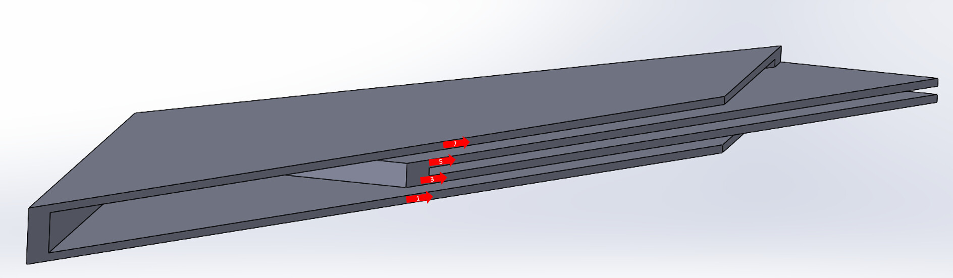
I did a read through of this a couple of times to wrap my head around the corner pleats, so I am probably going to start with a slightly expanded unit that I can use to “collapse” as flat as I can get, with the multiple layers of the corner pleats of that design.
I went over to get some measurements of it, but it was pretty busy this morning. That’s fine - I don’t need exact measurements right now. I can work on the bellows generic shape and just design it parametrically so that I just have to put in the correct height and width dimensions and it updates automatically. The length will just be the number of individual pleats of the “assembly”, plus the mounting geometry on either side.
Oh, yeah, there are probably going to have to be four different mounts for the gantry. Left side of gantry, left side of Z-carriage, right side of Z-carriage, right side of gantry.
I’ll see if I can make them both 3D printed (easier) and made out of folded sheet metal that can be cut with the machine. That will be little bit more difficult, since I do 3D modeling all the time and do sheet metal design maybe 2-3 times a year.
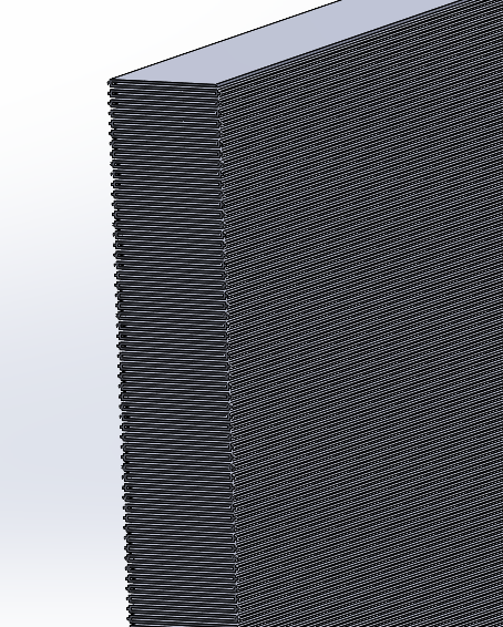
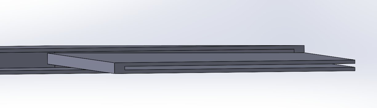
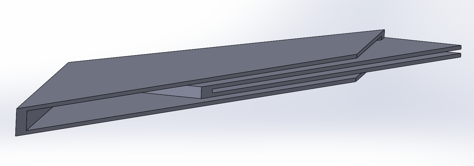
that’s some damn fine modeling, one other trick was modeling it in a relaxed state with .2or .4mm distance between folds to make layer height not an issue as there was alot of mixing and issues people went through during prototyping.
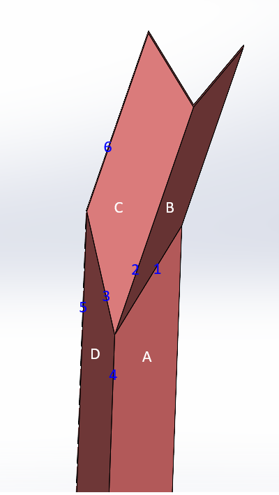
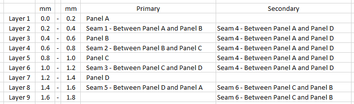
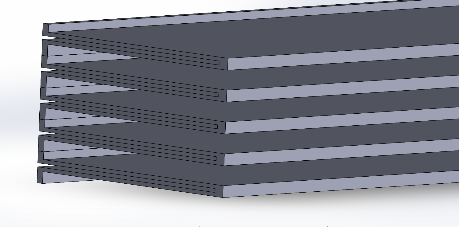
Thanks! Flattening it is a bit more difficult (as you and others have already found out) because I keep attaching the wrong seams to the wrong panels. I need to just look at the demo and get some paper and just sketch each layer.
I thought I got close, but discovered I attached a seam that should not have been attached to a panel side, and now I am back to layer 2 of 8 or 9 again.
I like SolidWorks. Been using it for 7-8 years now. I use CATIA at work (15+ years), and they have a similar enough feel I can go back and forth pretty easily now. Just have to remember different names for the operations in each one.
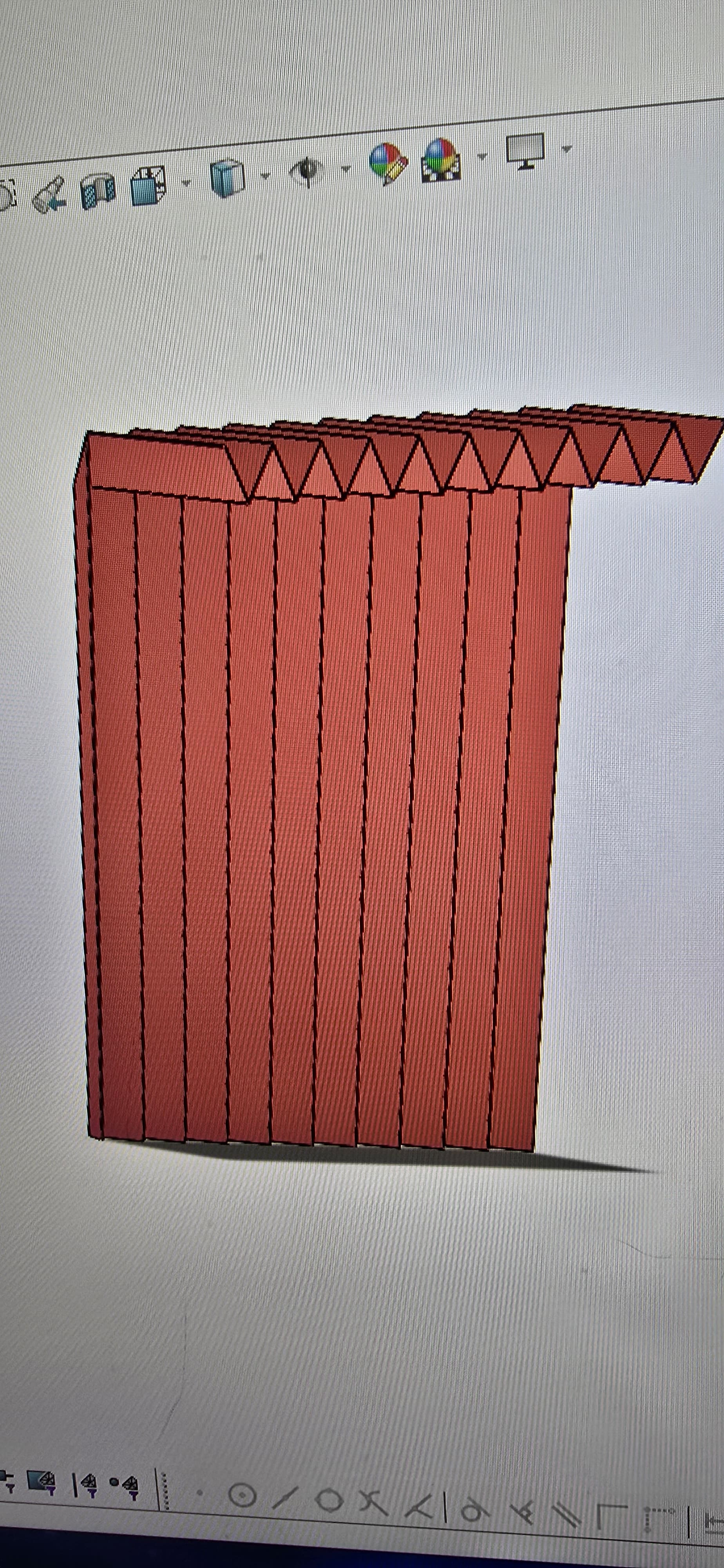
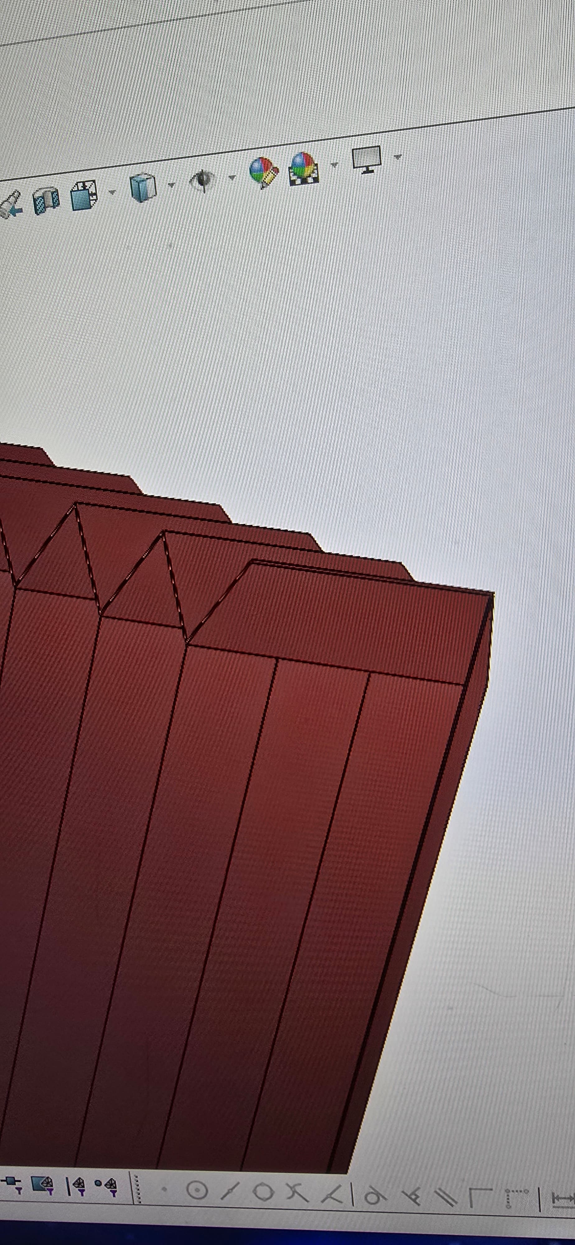
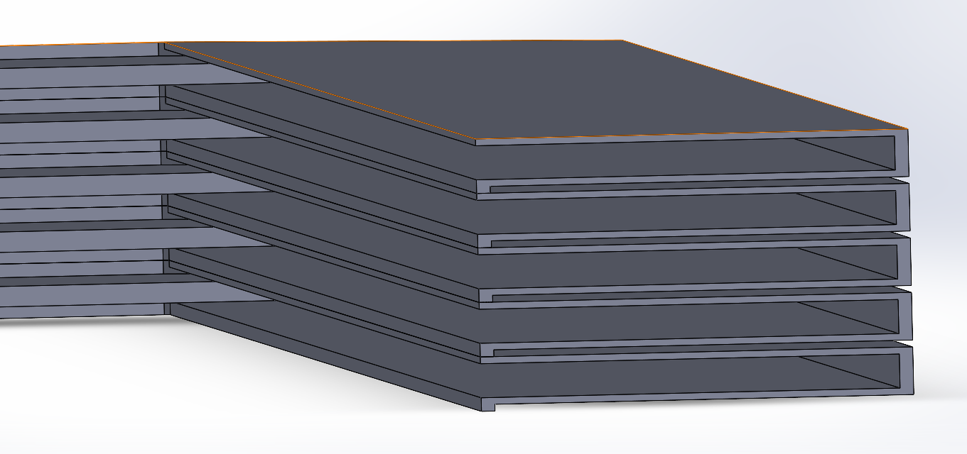
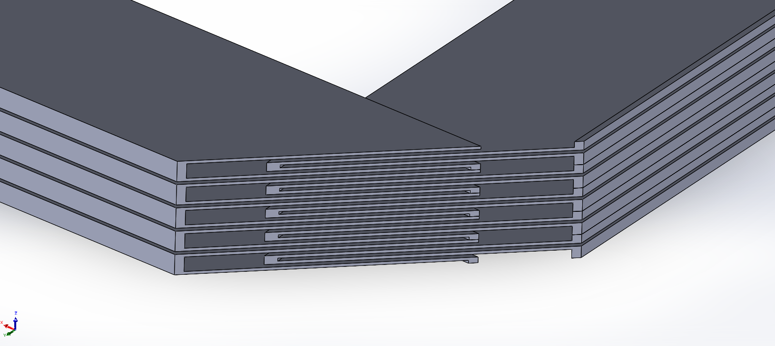
I still need to add layers 8 and 9, but figured I’d post this. Those two layers are only needed for attaching this undividual unit to the one next in the array of them, but not needed for printing just this one.
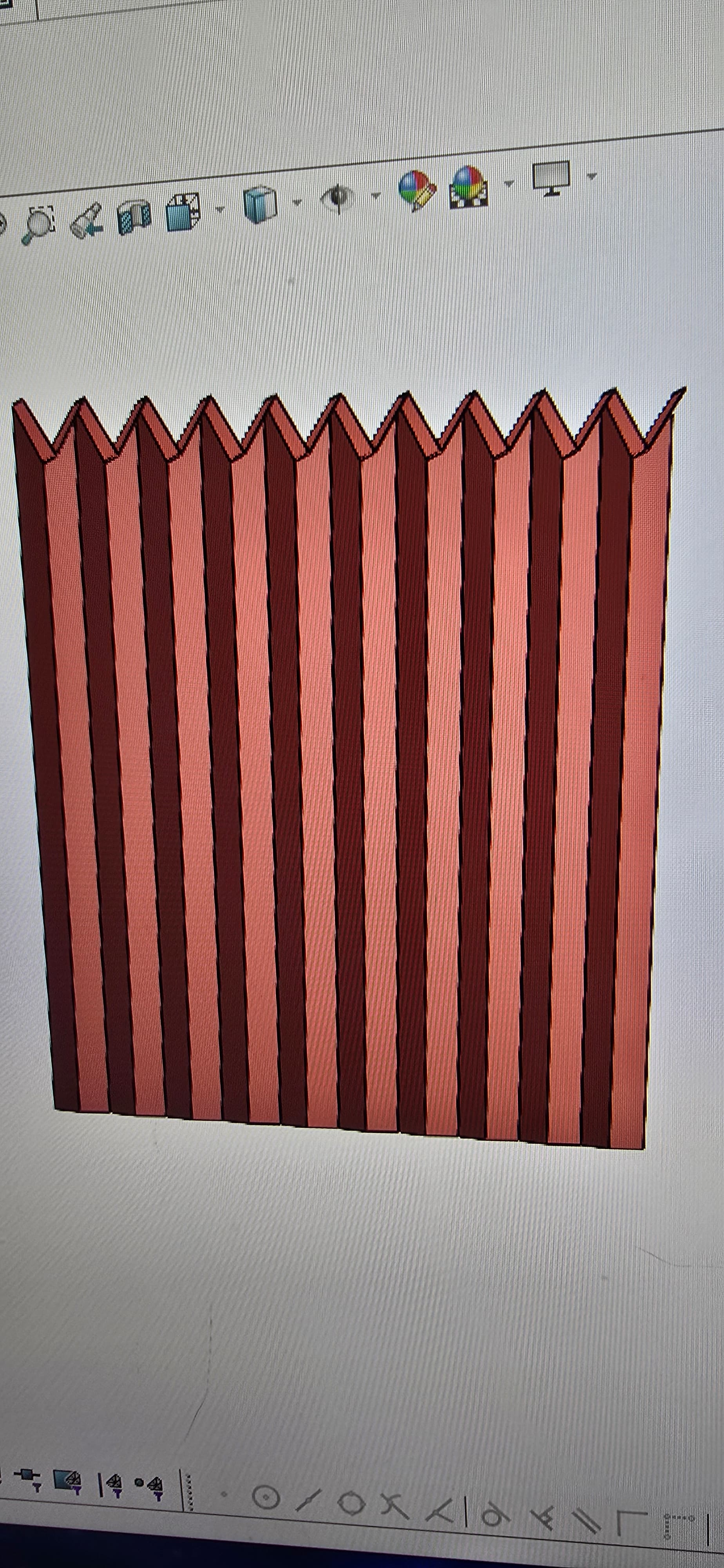
Had to add a few “hinge” strips to the first couple of layers, and I think I have the TPU portion done. Now, I just need to create the model with the PLA supports, since I don’t trust the slicer to make them properly for me.
Before I make the PLA support layers, I am going to go back through the TPU model and make it parametric, so I don’t have to do it more than once.
SolidWorks let’s you assign variables to just about everything - except layer height. So, to get around that, you have to create planes, and then do the extrude “Up to surface” instead of a dimension.
I want to be able to change the layer height in one shot instead of having to change each of the 9 or 10 layers individually. Also, changing the width and height of the bellows, as well as the height of the pleats and how wide the hinge strips are globally will be nice.
I’m familliar, it’s a bit of a meh system compared to fusion because I don’t like typing Dimension1@sketch3 and hooking things up afterwards but if you assign it as you go it isn’t bad.