I am hoping someone is familiar with this and can tell me how to fix it or why pro is doing this.
I have done a fair amount of 3d work making clocks and such so I am a little aware (I thought anyway) that when pro does the roughing and finishing path it should go to the bottom of the project and work its way up. I figure thats the way its supposed to work anyway.
But on a few occasions the x-axis will go to the left of the project, cut out about an inch wide strip then go directly to the bottom and start where its supposed to start.
By the time it comes back up (for whatever reason it is at a slightly different depth) it avoids its original strip of cut and goes around it and by theme its finished I have a 1 inch strip of wood on the left side of the project that does not match??
Does anybody know what that is and how to stop it or have they had a similar experience.
I have been thinking of using carbide motion wandering if that will stop it cause, if I know what I’m looking at, when I zoom in to see the tool path I don’t see anything similar.
for example, I am making a 45 record with all the grooves. At the start it swung to the left, did its strip, and went straight to the bottom like it should. I checked out the tool path and brought up the record. It shows the tool path swinging over to the left then but it doesn’t show it coming back out and going to the bottom so I don’t know If I am looking at the right orientation of the round record.
So, in short, I cant figure out whit cuts a strip of wood, goes down, comes back up and goes around the original strip.
Additionally, the other day I cut some wrenches. All it supposed to do was cut around the edge and carve out the wrench and another tool path was going to cut it out. All of a sudden the tool path went straight down on the side of the wrench and put a hole on the edge where I never could get it out.
I did see it on the image but again can’t figure out why it just dived into the side of the wood on one particular spot (2 spots actually). It was out of the norm for the rest of the carving and it shouldn’t have done that. How do you prevent or change stuff like this?
Can you share one of the files you’re having trouble with? If you don’t want to share publicly, private message or send it in to support@carbide3D.com and they will take a look.
These are pretty simple algorithms, and should behave as you expected if the boundary is a simple shape. When the boundary has some complexity to it, it has to figure out how to cut everything given the parameters supplied.
Maybe there is some left over geometry in your model with a toolpath assigned that you don’t notice. Zoom out to check?
And what file would that be?
It was the first time that I worked with that .stl
And I only use carbide create pro. Haven’t used any other program to have anything left over?
As noted in the other thread where you posted something similar, your comment is a bit harsh especially coming from someone who has self admitted to having invested a whopping 2 weeks learning the tool.
Everyone has different tastes and capabilities. I like CATIA as a 3D design tool (too bad I can’t afford it). I hate Sketchup because my brain just isn’t aligned with the way it works. That doesn’t mean Sketchup is junk as obviously a lot of people have done really amazing things with it.
Likewise a lot of people have done some really amazing things with Carbide Create. Vcarve has some very nice capabilities that I would like to see implemented in CC some day, but that doesn’t make CC junk.
If you have some more useful constructive criticism or specific feature requests bring them up.
I have ran aspire at my work for years. yes I tried to give create7 a chance and learn it as others were saying how user friendly it was. I found it mundane and difficult to use. The lack of options in the 120$ pro version I purchased was lackluster as well. So I bit the bullet and bought vcarve pro and was running near perfect tooling paths within the hr. I was running create on same svg file and the lines, curves etc. were messy. so yea worth every 699 1 dollar bills to run clean paths.
The C2D file from carbide create
No problem.
I’ll have to share it in the morning. It is going to take a while to correct this mistake. I’m cutting now (for some reason can’t upload the file. Maybe to far away? )and I will have to recut it during the night.
I tried to upload the c2d file but I’m getting a message saying the file is too big to upload.
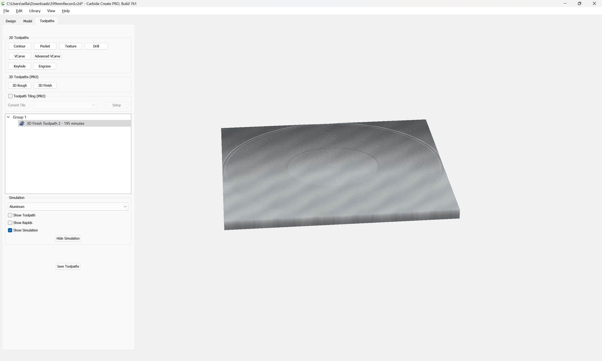
Here is a picture of what I’m talking about. I am making a record and when I preview it it only shows one rapid movement and then goes back and forth like its supposed to.
But when I load the file there are actually two rapid movements.
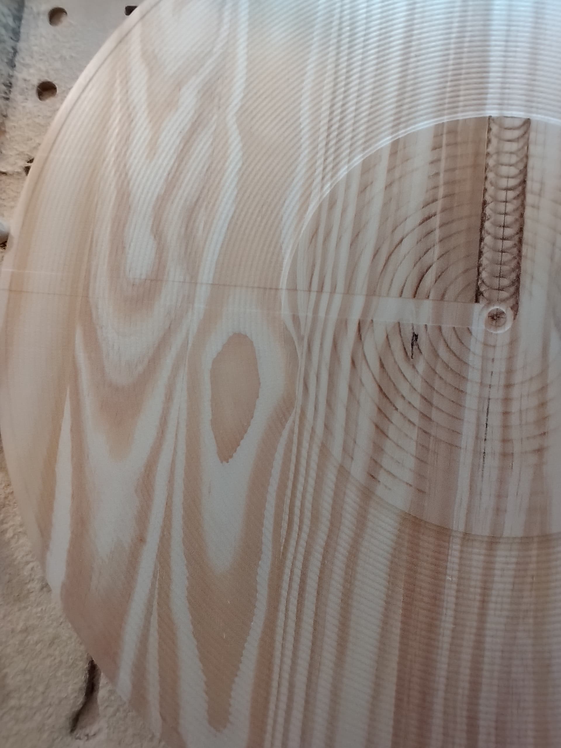
First it goes from the center to the left side of the circle and goes back and forth for about an inch. Then after that it leaves that area (leaving the portion you see on the left) and goes to the bottom of the circle and finally does what it is supposed to do. When it gets to the first part of the cut (the one it wasn’t supposed to do) it goes around it and continues till its finished The effects are what you see here. An unmatched portion that clearly digs too deep or just does not match.
It does it to all .stl’s that I do. Until now they match but I am having serious trouble now and it affects other projects.
Do you have One Drive, Google Drive, somewhere you can upload & share it?
It definitely shouldn’t be doing that. But it could very well have something to do with the geometry and the tool path seeing something it thinks needs to be cut.
This file came in from support — since there are a couple of things with it, and since support downsamples screen grabs to the point of illegibility, we’ll work through this here.
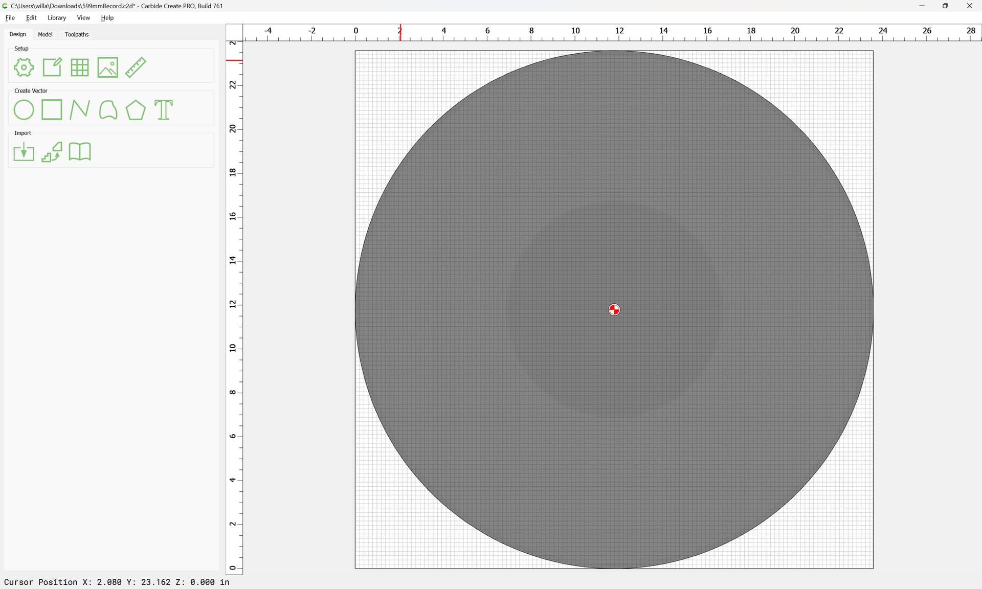
The file in question is an 8.99 MB .c2d file which has 1 3D component (apparently imported from an STL)
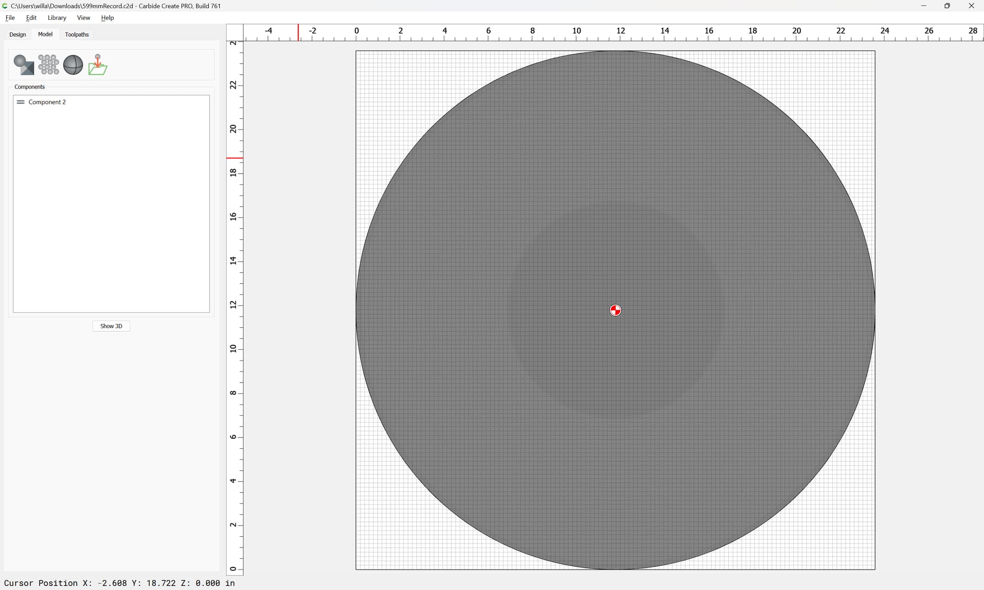
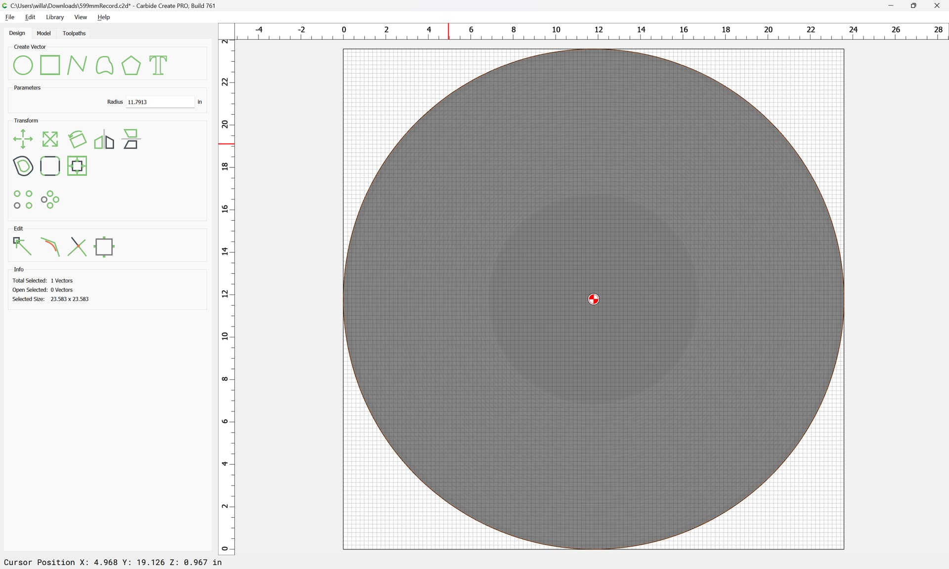
and 4 vectors:
which is odd, since there only look to be 3.
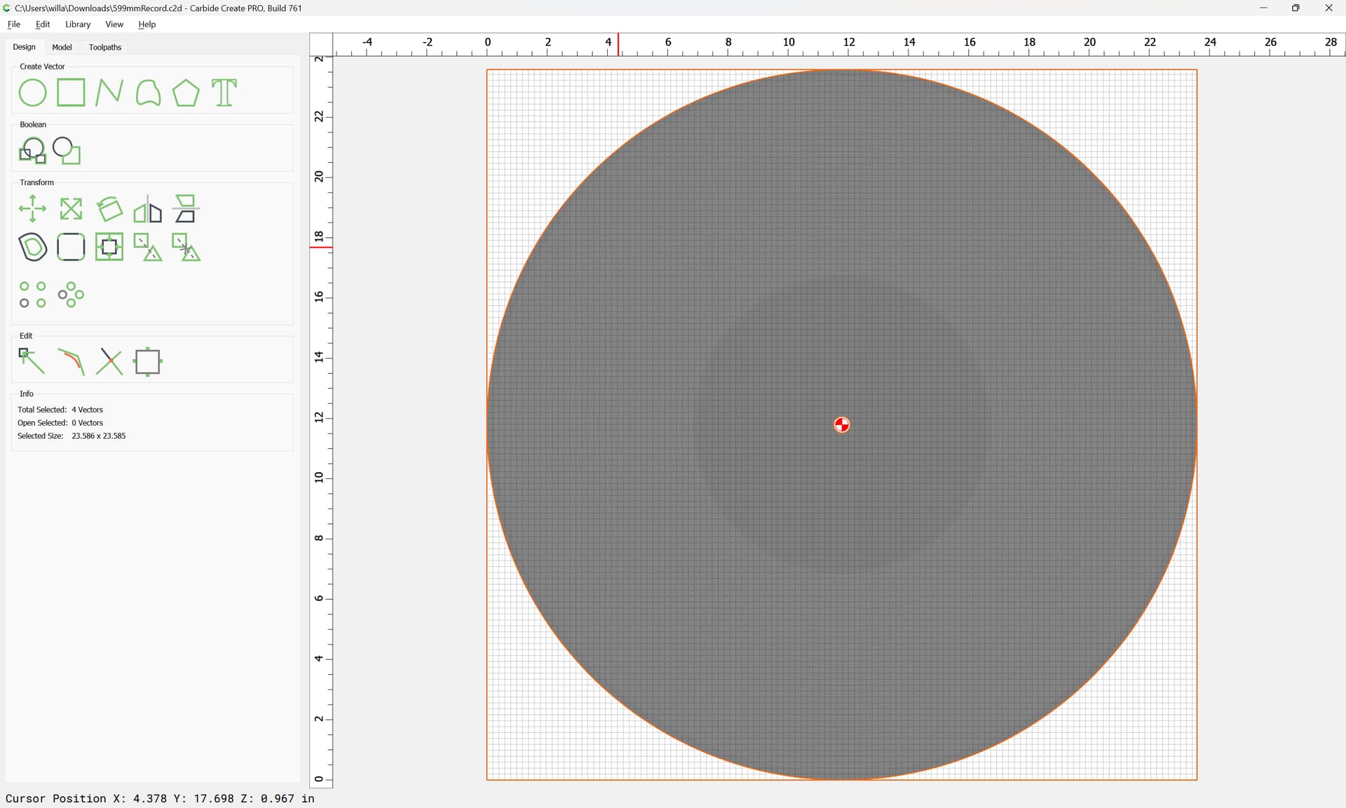
Further investigation reveals that one of the vectors is doubled:
and that the doubled geometry is what is used in a toolpath:
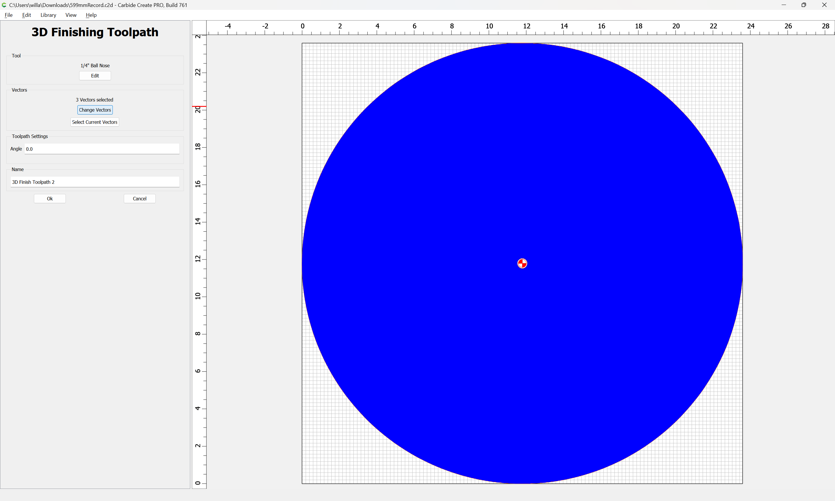
Going back to Design, shift-click on the central vector to remove it from the selection:
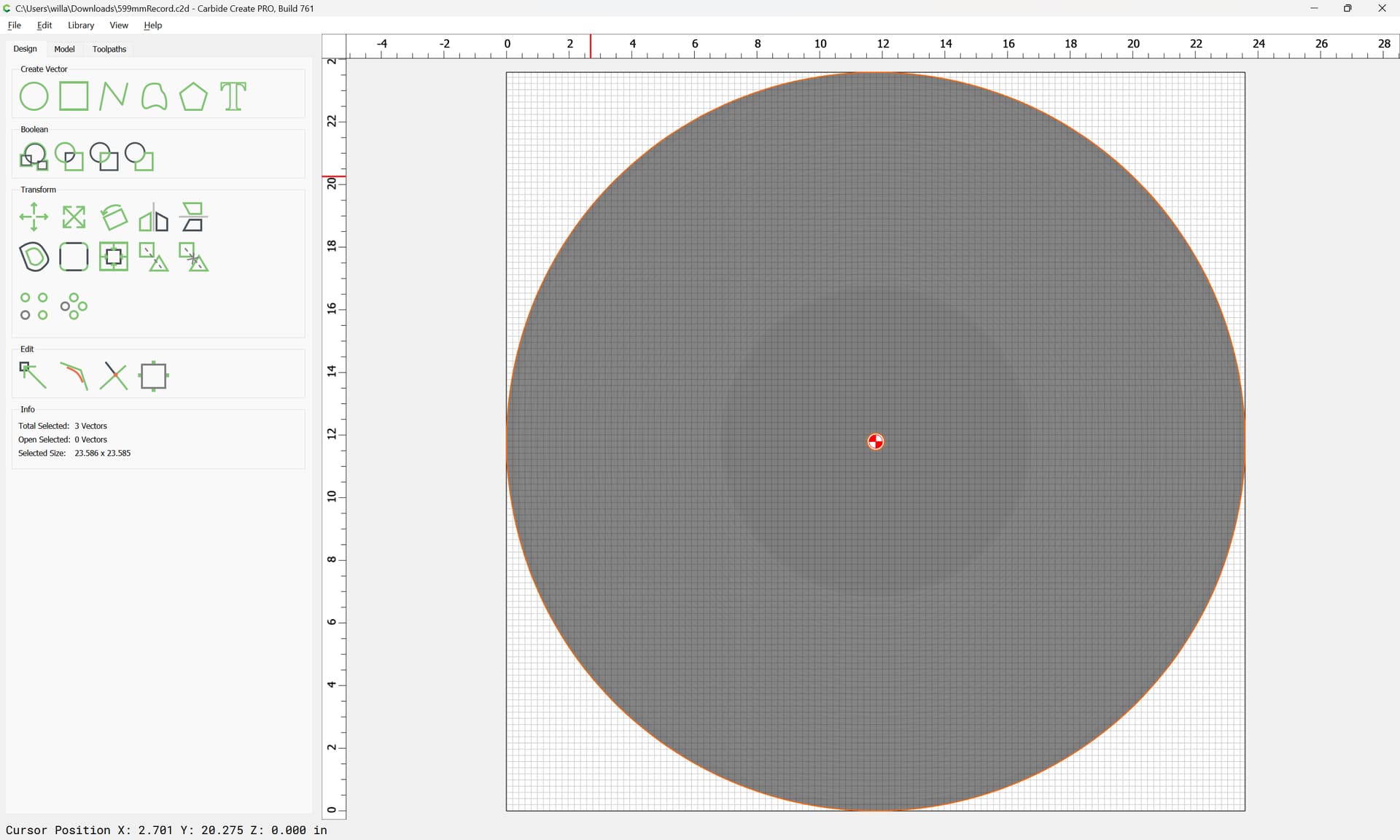
and delete it:
as verified by “Select All”

With that doubled geoemetry removed, toolpath generation is as expected:
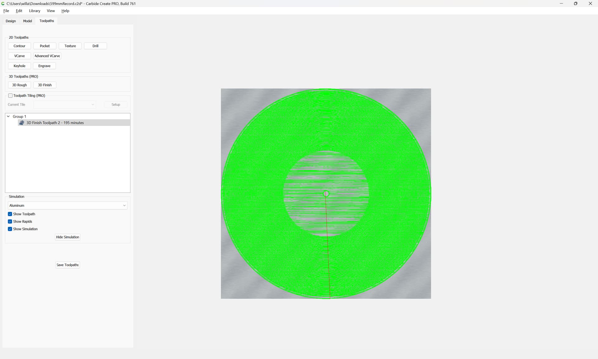
and predictable, and a cut should match the 3D preview:
If, workholding is secure, tool usage matches what is in Carbide Create, and feeds and speeds are appropriate to the tool and material and the job setup is correct, and the material being cut is able to hold the requisite detail.
This topic was automatically closed after 30 days. New replies are no longer allowed.