Hi
Recently I bought (rented) CC pro. I used some of the feature and am now going to do my first little 3D Carve, Wow that was a bit of a learning curve to bring in a simple STL file correctly. Still a bit fussy. However there is one item I just could not figure out. In the simulation, the step over looks like crap. I am using the 3d Roughing and Finishing, Would it not pick up the 3D 5% step over. I added my own bit and adjusted this value up and down, no change. It just keeps defaulting to the 2D stepover. The parameter seems to do nothing, Kind of like a light switch with no wires in the box
If I manually override it, the simulation looks good. So it is not a resolution thing. The paths are just not there.
What silly thing did I miss to get the 3D stepover to come up when using the 3D buttons ??? Or is my assumption wrong ?
I have spent many hours trying to figure this out and trouble shoot it. Its now time to swallow my pride and simply ask
It’s exactly like that. Very few of the parameters from the tool library are actually used in the toolpaths.
I think it’s pretty much just the geometric parameters (diameter, angle, shape)
So you didn’t miss anything, you just need to input your own stepover & depth of cut if they don’t match the defaults.
It’s a bug that has been reported to Carbide 3D. I have not received any information related to when it will be fixed, but it’s been a bug for a long time.
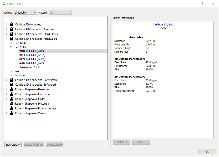
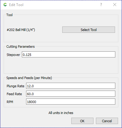
Bug: For 3D finishing toolpaths, choose ANY ball mill, doesn’t matter which one. For this example I will choose the 1/8" from the Carbide 3D-Shapeoko-Hardwood library…
Notice within the tool library, in the 3D Cutting Parameters, there is a setting named “Stepover”, which for this example has a value of 5%. So when someone selects a 1/8 bit with a 5% stepover the expected result is (0.125 * 0.05)=0.00625 stepover.
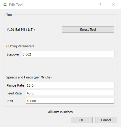
However, that is not what happens. After selecting the tool instead of using that formula the 3D finishing stepover always defaults to 50% of the tool width. And there is no relationship between the 5% vs 50%. In my own tool libraries I have altered that setting to 10% and it still results in 50%.
Pick a 1/4 ball mill …
… I’ve never noticed it returning anything other than the 50% value, and it’s an easy mistake to not notice until you start looking at the render or actually cutting.
I feel like I have reported this bug multiple times, first time was 2023-05-02 @ 3:20, last time was 2024-03-03 @ 1:34 using beta 768.
I did some more looking and I see a thread almost a year ago on the same thing and at that time it was also reported as a bug We have had new versions since then so Hmmm
I am a fan of C3D. However some times people are too used to things and the way they work so it makes sense to them but maybe not to people like me It gives every impression that this will do something Based on that I spent hours
It is like buying a new car and there a switch on the dash that does nothing and when you ask they say yep just don’t touch it
Maybe they should have said for reference or future. then I would not have wasted hours of my time
So let see the bit is in inches so I have to convert that to MM then take 5% - 10% of that and then manual enter it for every bit and by default it switches back to 2D I could see missing this and oopsing a cut
Maybe it is me but it seems a bit of a PITA with high probability of an error for what could be a easy fix. It seem to a simple person like me that the coding is pretty simple.
I did say this is my first 3D try. Seems to me it would be nice to display the stepover in dimension and in percentage. Also maybe to be able to enter the percentage and have it calculate the stepover. As we normally are using percentage to start with then convert. or both I.E 1.23mm or 40%. A percent sign might be a nice feature for the stepover field I see mm or in or formulas dont work in this field.
In addition When loading the STL, what a pain as I am new to it and learning but I cant count the amount of times I had to delete and import the STL as I can not move it around or make any changes. Delete and start again. Well you can move the outline around and make a real mess, the image does not stay attached to the outline.
I really should hold back but all that is going through my head is this is the paid version ??? And remember I do like C3D maybe it just a learning curve but what frustrating night.
Awesome write up Yep seems like an opportunity to make it make sense. Either more clear (reference only) or make it work. Then people would not spend hours or maybe I am the only one
Funny I am reminded of Musk’s 5 Step Engineering Algorithm at Tesla and SpaceX
Question every requirement
…
Musk: “Requirements from smart people are the most dangerous because people are less likely to question them. Always do so, even if the requirement came from me. Then make the requirements less dumb .”
…
So we are just questioning Is it a bug or an opportunity.
Yes, we have made note of it to look into how to handle it.
Correct, manually changing this is the work-around — at a guess, the view is that that is a sensible/workable default, and if folks are changing it, they will have to do this on a per-project basis and that that seems the most suitable option (since the alternative would be cluttering up the tool list with many different stepovers for a particular tool).
So if I want a 5% overlap I have to get out a calculator for each bit
IE
1/4 ball convert to decimal = 0.250 convert to MM so x 25.4 = 6.35 MM
Then 5% stepover so x .05 = 0.3175
For each time I touch a bit
I would not say it is a reasonable work around but yes it works
A very easy fix is:
I would suggest that we have already created fields that we can do math in, it just has not been applied to this field, So the programing is already done just not added to this field. IE 0.25in x 0.05 should calculate it for you. Easy pesky as a work around.
I would like to see a way to enter the overlap percentage as that is normally what we work with. So simply enter " 5% " which takes the bit size and calculates the 5% overlap. Yes you would have to program a new operand. The % operand might be nice to have in all field calculations, ie 50% of the thickness. As we know the “%” is simply a conversion to 0.50 but it reads easier to the user and that is what we are trying to do as we are all not math savvy
And yes the end goal would to be that in addition to doing math in this field that it defaults to the 3D bit overlap when doing a 3D operation (rough and finish) .
I too am a CC pro new user. I have had many of the same issues trying to get a 3d relief file to work. I have come to the conclusion that this functionality in the software is not its strong suit. I feel bad putting this out there but I decided to try “Carveco” software. There is a hefty learning curve but I’m getting there. 3d Files that I purchased actually load and are modifiable. I am excited to see if I can produce quality 3d relief projects. There are many utube videos available that are very informative. The software is $15 a month and you can cancel any time. Figured it was worth a try, liking it so far. I am still a fan of CC but not so much for the 3d aspect.
I also like what C3D is doing.
Yep I am learning some gotchas (in my mind) in CCpro, I believe it is just a learning curve on things I need to look out for. CCpro does has some nice all round features, a little of everything Maybe not so strong in some areas though.
I too have downloaded alternatives to compare. As much as I like supporting C3D I can only afford one And maybe not even that I will have to do a comparison to see what works best for me and what makes sense for me and the work I want to do.
I personally am not a fan of renting software just not something I was used to, but this seems to be the way of the future
I wish there was a hobby use verses business use version. I have too many hobbies that I bounce around from and it is challenging to afford them all I make no income from any of them, Just hobbies and volunteer services .
One thing I just learned to look out for is to make sure the roughing bit can get to within the roughing tolerance other wise the finishing bit will dive into the martial too far. In my case a 1/8in bit did 14 mm drive and then it started moving, ouch that was a lot of wood. Protentional bit breakage.
Interesting though, to compare, I downloaded Vcave and the same condition appears to occur by looking at the simulated toolpaths.
I guess I am too new to 3d Carving, still 3D stupid :), and this is just something I need to watch out for.
I do a bunch of 3D printing and I am used to it marking things in Red when it does it validation check, it does not fix it. it just shows that there may be an issue in this area. IE too much over hang without a support. Which is kinda the additive printing condition verses the subtractive caving condition.
I would think that if the roughing bit could not get the martial within say 2x the tolerance, (2 x 0.5 mm) the RED would show in the preview. But it appears not to in either.
I am tiring to engrave small lettering into an aluminum electrical control panel I am creating.
I did a bunch of test samples and didn’t get what I was expecting
Then I notice that when I adjust the Cut Depth it also changes the DOC in the tool. And vice versa. And it gives no indication. It caught me as I selected the tool CC 502 Engraver, I looked at its depth of cut 0.002in I then set the the Cut Depth 0.010 in. I never went back to the tool, why would I.
In the Simulation it does not really show the tool path well for Engraving paths. It shows plunge paths but not the tool paths. The non engrave paths show fine.
I get it if I had a drag engraver then there would only be one tool path depth but for a vee etcher, can you not have multiple depth passes ??
I can create a Advance VCarve. but that is not the bottom finish I want. I was trying to get a a crosshatch design.
Did I miss something ??
Again I have several hours into this.
Or is this a feature ??
The engraving path, regardless of the tool (type) you use, is a single pass path.
If you change DOC or Cut Depth in either location, it updates the other location.
If you want multiple depths, you have to create multiple paths & change the depth.
If you’re having trouble seeing the path, uncheck “Show Simulation” and you will just see the path.
The fact that PCB Engravers are named as such is an unfortunate overlap of use in the English language.
The Engrave toolpath is not meant for use with the PCB Mills (As I refer to them).
Instead, the “Engrave” toolpath is specifically for Drag Engraving with the MC Etcher.
If you want to do lettering with a 501 or 502, use the VCarve toolpath. You’ll get outstanding results in aluminum. I recommend the 501 for that type of work.
@Tod1d that is a good work around.
I guess my thing is that it is not intuitive and I keep wasting hours trying to figure it out or going down a rabbit hole CC was easy to figure out. Maybe its just me but it been frustrating to jump up to CCpro. some things have been great, Others have been a learning experience. I would think for the paid version it would be tighter / more clean
Still a great program and features once you figure out the idiosyncrasies The frustration will pass
In another thread I suggested the hint box like so many other programs have. Which would have informed me that Engraving is a one pass deal. Verses every other Cut Depth entry. Currently it leads you into plunging your engraver
This is the second possible catastrophic path I have found in CCpro in a week
It could have said that it was changing/syncing the depth of cut to match the Cut depth as this is a one pass toolpath.
Still not sure why you can use multiple passes for a Vee Etcher. I was looking to etch into the aluminum about 0.001 of an inch. So Manual passes it will have to be Now we know
Thanks @KevBarn14
I agree and this also speaks to the clarity I spoke of. C3D does a great job at trying to keep a clean work flow however some of the wording choices seem to take you down a oops path And yes they have the 501 and 502 in the etcher category so I can see why it might confuse people.
I agree a “Drag Etching” is far different then a “Pocket Etching” or “Mill Etching” if we can call it that
I felt the cross hatch bottom finish was a better look then a pocket contour paths in aluminum. I get it now, Thanks. It might be a feature to add more choice to advanced Vcarve bottom finish
Oh well I know now however I still believe better choice of words and hints would have saved me hours.
For now I might trying stacking the etching paths as @Tod1d suggested
I feel smarter today then yesterday, so it is a good day
There are some goofy things to get used to. But it’s still a pretty capable tool for free or cheap.
I thought maybe you could use the texture path with settings for a flat texture, but it doesn’t honor the DOC either. Instead it keeps changing it back to the default 0.118"
Only other thought would be to draw up the entire path & used contour. ???
Better if all the paths behaved the same & honored the DOC & Max Depth. We can always set DOC greater than or equal to Max Depth to get a single pass if we want one. And for the Engraving & Texture paths it could still default to 1 pass.
Thanks, I set up a test sample of about 6 ideas and will see which one I like.
Yes Love CC, I had no problem figuring it out. A couple of things as I said could be labeled better.
CCpro has some great features. But a bit of a frustrating learning curve
If you need someone to stupid proof then I am your guy
To be honest I have downloaded Vectric V-Carve Desktop and am looking at it. Too bad you cant actually carve with it before you buy it
I bought a one year of CCpro so I have some time, however my procrastination is pretty good